
Dark Detector
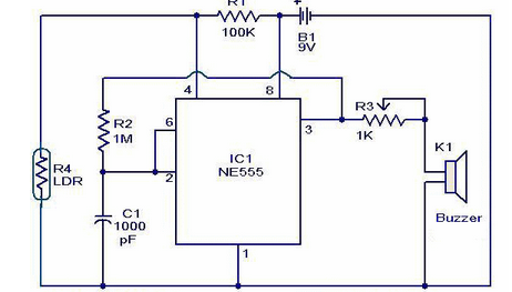
The dark detector circuit operates by utilizing a light-dependent resistor (LDR) as the primary sensor to detect changes in light intensity. When the light level falls below a certain threshold, the resistance of the LDR increases, which in turn affects the voltage at the input of the timer IC.
Typically, a timer IC such as the NE555 is employed in this circuit configuration, functioning in monostable mode. In this mode, the timer is triggered by the voltage change caused by the LDR. The output of the timer IC can be connected to a small speaker or buzzer to produce an audible alarm.
The circuit may also include a potentiometer to adjust the sensitivity of the LDR, allowing for customization based on the specific lighting conditions of the environment. Additional components may include resistors and capacitors to set the timing duration for how long the alarm sounds after being triggered.
Power for the circuit can be supplied through a standard battery or power adapter, ensuring that it is suitable for various applications, such as security systems or automated lighting controls. This dark detector circuit is a practical and efficient solution for alerting individuals when a room becomes dark, enhancing safety and awareness in various settings.The dark detector circuit shown here can be used to produce an audible alarm when the light inside a room goes OFF. The circuit is build around timer IC N.. 🔗 External reference
Related Circuits
The White's Classic I was a straightforward and user-friendly metal detector, making it suitable for entry-level enthusiasts. It featured a simple design with only an on/off switch and a discriminator adjustment knob. Although it lacked depth, it was capable...
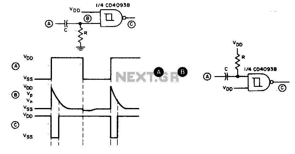
This circuit generates a brief negative-going output pulse in response to each positive-going edge at the input. The input signal is coupled to the circuit through a capacitor (C), and the duration of the output pulse is determined by...

The motion sensor circuit depicted in Figure 1 operates when a 12-volt power supply is applied to the input point. The motion sensor circuit is designed to detect movement and trigger a response based on the presence of motion...
A gas leak detector circuit that detects the leakage of LPG gas and alerts the user through audio-visual indications. The circuit operates off a 9V PP3 battery. A Zener diode is used to convert 9V into 5V DC to...
This circuit is a motion detection sensor that utilizes a light source and detector as an infrared motion detector. The motion sensor employs an infrared LED and a phototransistor. Since it relies on light, the sensor's sensitivity can be...
This weblog discusses electronic circuit schematics, PCB design, DIY kits, and electronic project diagrams. The rain detector operates on the principle of an astable multivibrator using the 555 timer IC, which is equipped with a sensor capable of detecting...