
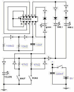
Whites Classic I metal detector schematic diagram

The White's Classic I metal detector is designed as a basic yet effective tool for novice metal detecting enthusiasts. Its simplicity is a key feature, allowing users to quickly learn the fundamentals of metal detection without the complexities found in more advanced models. The operational framework is built around a minimalistic interface, which includes an on/off switch and a discriminator knob that enables users to filter out unwanted signals, thereby enhancing the detection of valuable items.
The circuit design incorporates four transistors, which are essential for signal amplification and processing. The MPS3638 and MPS6520 transistors function primarily in the signal path, while the MPSA13 and 2N3904 transistors may be utilized for switching and additional amplification tasks. The use of a CD4066 digital switch allows for effective control of signal routing within the detector, contributing to its overall functionality.
The three LM393 dual comparators serve as critical components for comparing input signals, facilitating effective discrimination between different types of metals based on their conductivity. This capability is crucial for users who wish to avoid false signals from unwanted metal objects. The operational amplifiers (LF444, LF441, and LM358) are employed for signal conditioning, ensuring that the signals processed by the detector are clean and accurately represent the detected objects.
Power regulation is managed by the LM2930-8, which provides a stable voltage supply necessary for the reliable operation of the detector's circuitry. The choice of 1/4 watt resistors with a +/- 5% tolerance ensures that the circuit operates within acceptable limits, while the specified capacitors are selected based on their capacitance values to optimize performance. The distinction between aluminum electrolytic and polyester film capacitors is significant, as it affects the frequency response and stability of the circuit.
In summary, the White's Classic I metal detector, while basic in its design, incorporates a thoughtful arrangement of components that allows it to perform effectively for entry-level users. Its straightforward operation, combined with reliable circuitry, makes it a valuable tool for those beginning their journey in metal detecting.The White`s Classic I was a very simple, easy to use machine, ideal for the entry-level detectorist to pick-up-and-go. It was a simple detector with no bells or whistles, only an on/off switch and a turn knob for a discriminator.
It did not have much depth but it did find coins, jewelry and relics in the hand of a skilled hobbyist. While the Class ic I was good for its day, there are now better beginner metal detectors on the market. The detector used 4 transistors (MPS3638, MPS6520, MPSA13 and 2N3904) and only a few ICs: a CD4066 digital switch, three LM393 dual comparators, LF444, LF441, LM358 op-amp ICs and an LM2930-8 3-terminal positive regulator. All resistors in the schematic are 1/4 watt, +/- 5% tolerance and all capacitors are in microfarads unless marked otherwise.
Capacitors greater then 1 uF are aluminum electrolytics. Capacitors less than 1uF are polyester film type. Capacitors marked with a triangle are stacked polyester type. Areas inside dashed lines are not located on the main PCB. 🔗 External reference
Related Circuits

The circuit utilizes the MAX1576Y charge pump white LED driver, capable of supplying a total current of up to 480mA across two groups (n = 4 white LEDs). Each white LED in the flashing group can draw a maximum...
This circuit is the electronic emulation of the I Ching, a form of divination originating in China. In the classical form, the response is obtained by the manipulation of 50 sticks or, more practically, by tossing 3 coins. The...
This circuit is designed to detect incoming calls on a cellular phone, even when the phone's ringer is turned off, by utilizing a flashing LED. The device should be positioned a few centimeters away from the cellular phone, allowing...
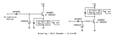
The two circuits illustrated show the operation of opening a relay contact shortly after the ignition or light switch is turned off. A capacitor is charged, and the relay remains closed until the voltage at the diode anode rises...
Is there a recommended schematic for the 211 / VT4C similar to the Air Tight ATM-211? It would be preferable if it does not include an interstage transformer and 6SN7. The request pertains to the design of an audio amplifier...
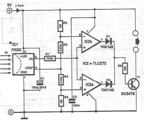
This infrared detector circuit is designed using the PID20 integrated circuit manufactured by Siemens, which converts thermal radiation into electrical impulses. It includes an operational amplifier and several electronic components. The output signal at pin 3 is compared with...