
darkroom timer with PIC 16F84A
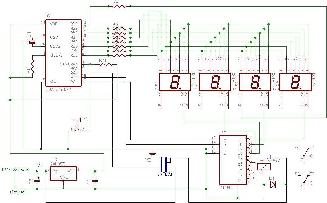
The proposed timer circuit is a compact and efficient design aimed at controlling exposure time in a darkroom environment. The core of the circuit is a microcontroller, specifically a PIC (Peripheral Interface Controller), which serves as the main processing unit. The microcontroller is programmed with firmware that manages all the timer functions, enabling a single pushbutton switch to control the entire operation. This design choice minimizes the complexity of the user interface, making it user-friendly while maintaining functionality.
The timer features a four-digit LED display, which provides a clear visual indication of the countdown timer. This display is driven by the microcontroller, allowing it to show the remaining time accurately. The inclusion of a second integrated circuit (IC) could serve various purposes, such as providing additional timing functions or handling input/output operations more efficiently.
A resistor network is employed to interface the pushbutton switch and provide necessary pull-up or pull-down resistances, ensuring reliable button presses are detected by the microcontroller. The capacitor in the circuit can be used for debouncing the switch or for timing purposes, depending on the specific design implementation.
For power supply considerations, the timer circuit can operate on batteries, which is suitable for portable applications. To control the exposure light, a solid-state relay (SSR) is utilized. This component allows for the safe switching of higher voltages or currents without mechanical wear, thereby enhancing the reliability of the timer system. If a wall adapter is preferred, a simple voltage regulator can be added to the circuit, enabling the use of a "wall-wart" power supply while only introducing a minimal number of additional components.
Overall, the design emphasizes simplicity and efficiency, making it an ideal solution for darkroom timing applications. The accompanying schematic, parts list, and firmware notes further assist in the construction and implementation of the timer circuit.I tried to design a timer that would do everything it needed to do but with the smallest number of pieces and simplest mode of operation. It only needs the PIC, a four digit LED display, one other IC, a resistor network, one pushbutton switch and a capacitor.
It can run on batteries if you use a solid state relay to turn the exposure light on and off thereby adding a minimum of parts to make a fully functional darkroom timer. A simple regulator would add only a few extra parts and allow the use of a "wall-wart" for power. All the functions are in firmware, allowing the use of one switch for control. I sketched in the schematic in Eagle format and here's a jpg image, too. This text file has the parts list and some notes to help you build the timer. Here's the firmware. You 🔗 External reference
Related Circuits
Speaker relay delay controlling circuit for audio amplifier The speaker relay delay control circuit is designed to protect audio amplifiers and speakers from potential damage caused by inrush current or transient signals during power-up or power-down sequences. This circuit typically...
A small circuit designed for various time measurement applications. It features an audible sound signal from the buzzer BZ1 and has the capability to drive an external circuit through the optocoupler IC2, once the appropriate circuit is connected to...
This door open alarm electronic project is designed using a linear hall effect device and a 555 timer circuit. The project utilizes the TL3103 linear hall effect device for detecting the angle of rotation. The TL3103 is positioned within...
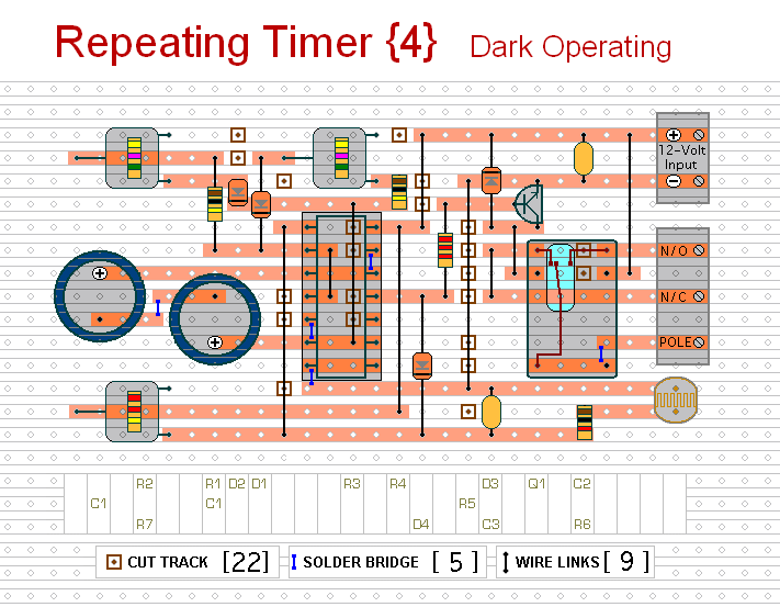
This circuit functions as the inverse of Repeating Timer No. 3. Its operation is constrained to the hours of darkness. The variable resistor (preset) allows for the selection of the darkness level at which the timer will activate. The circuit...
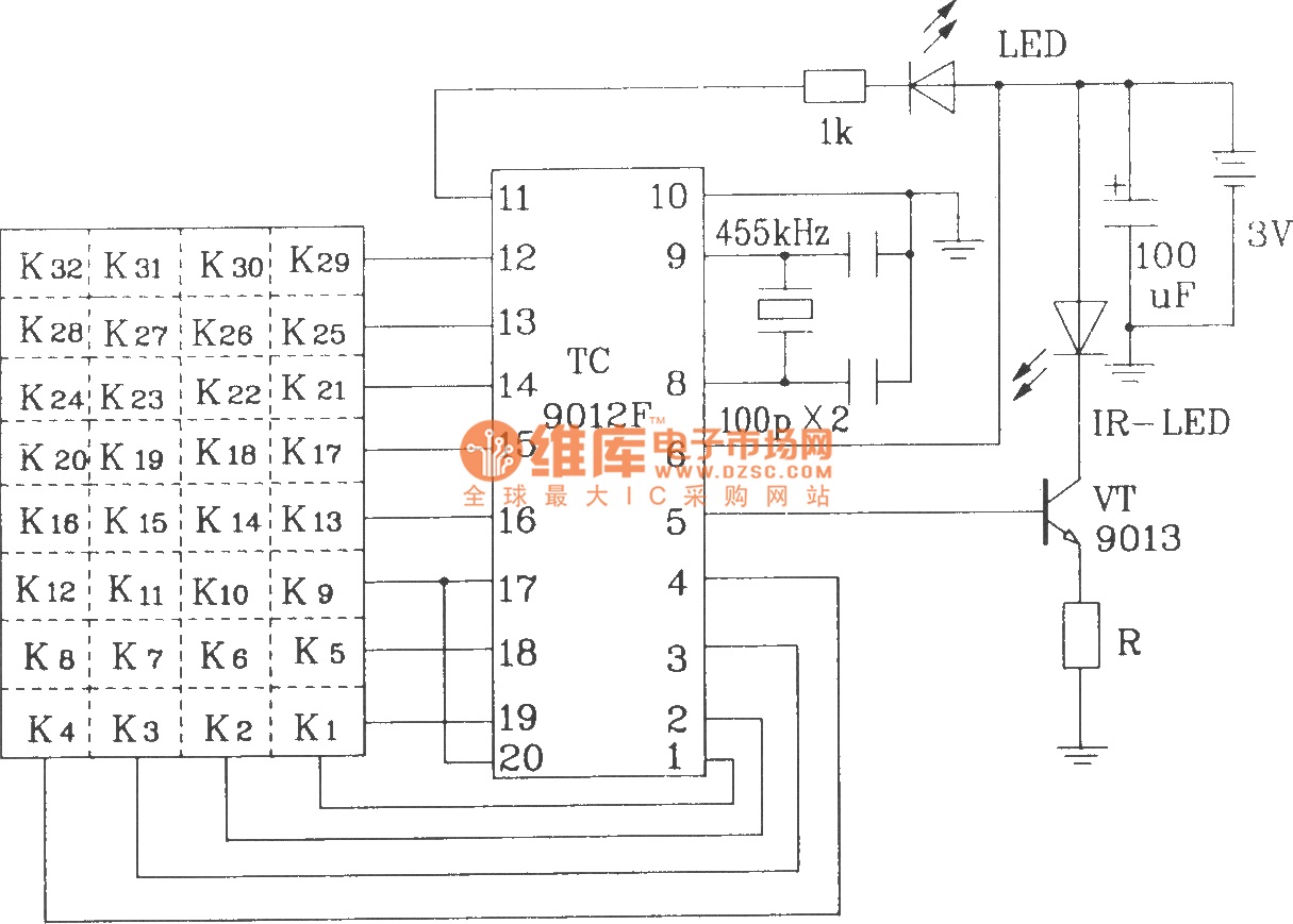
The TC9012 is a specialized off-screen remote control code transmitter. It incorporates an oscillator, divider timing generator, system code latch, data storage, key scan input, key scan output, and carrier control and output units. The internal 8-bit system code...
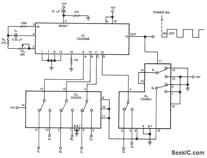
The timer circuit provides independent control of the output's on and off intervals, which can range from 0.055 seconds to 30 minutes, with minimal impact from power-line transients. IC1 is a CMOS programmable timer chip that features 24 ripple-binary...
Warning: include(partials/cookie-banner.php): Failed to open stream: Permission denied in /var/www/html/nextgr/view-circuit.php on line 713
Warning: include(): Failed opening 'partials/cookie-banner.php' for inclusion (include_path='.:/usr/share/php') in /var/www/html/nextgr/view-circuit.php on line 713