
repeating timer no4
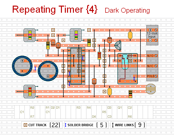
The circuit is designed to operate exclusively during nighttime conditions, making it suitable for applications such as outdoor lighting control or security systems that require activation only in low-light environments. The core component of this circuit is a light-dependent resistor (LDR), which changes its resistance based on ambient light levels. When the light intensity falls below a predetermined threshold, determined by the variable resistor, the circuit triggers its output.
The variable resistor, or preset, is crucial for calibrating the circuit's sensitivity to light. By adjusting this component, users can set the specific light level that will activate the timer. This adjustability ensures flexibility in various environments, allowing the circuit to function optimally under different conditions.
The output of the circuit can be connected to various devices, such as relays or transistors, which can control higher power loads. This feature enhances the circuit's versatility in real-world applications. For instance, it can be used to turn on garden lights automatically at dusk or activate security lights when it gets dark.
In summary, this circuit provides an efficient solution for controlling devices based on ambient light levels, with the added advantage of user-configurable settings for precise operation in varying light conditions.This circuit is the opposite of Repeating Timer No.3 . Its operation can be limited to the hours of darkness. Again - the variable resistor (preset) lets you choose the level of darkness at which the timer will begin to function.. 🔗 External reference
Related Circuits
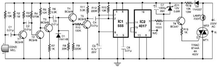
This 555 timer clap switch circuit electronic project is designed using common electronic components. The circuit operates from a distance of up to 10 meters from the microphone. The signal from the microphone is amplified by transistors T1, T2,...
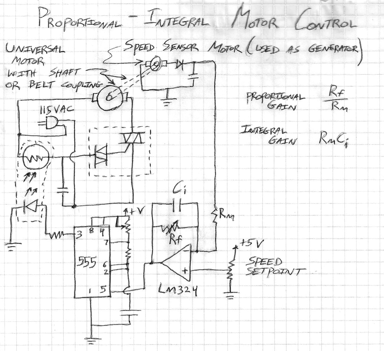
This is a motor speed control circuit that enables safe and straightforward regulation of 115VAC universal motors, such as those found in drill motors, blender motors, and other power tools. The motor is directly controlled by a triac-diac component...

Speed regulation is achieved by monitoring the motor current with resistor R17 and utilizing it as positive feedback to offset motor resistance losses. The gain potentiometer should be adjusted to just below the threshold where motor speed begins to...
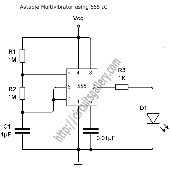
An astable multivibrator can be designed using a 555 timer IC, operational amplifiers, or transistors. The 555 timer IC provides accurate time delays ranging from milliseconds to hours, with the frequency of oscillation adjustable through simple modifications. This is...
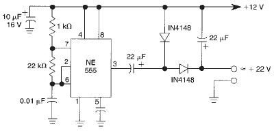
This voltage doubler circuit utilizes a 555 timer integrated circuit configured as an astable multivibrator. It can deliver a maximum output current of 50mA; exceeding this limit will result in a reduction of the output voltage. The actual output...
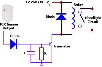
The circuit illustrates a 12V PIR sensor timer circuit diagram. Features include a 12 Volt DC supply, capable of activating a floodlight or other devices for a specified duration. The 12V PIR sensor timer circuit is designed to detect motion...