
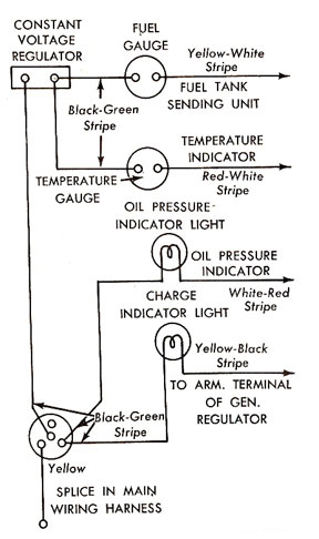
Dash Instrument Testing
One commonly overlooked aspect is the grounding system. Both the engine and chassis must be properly grounded for the gauges to function correctly. Ensure the battery ground wire is securely connected to the engine and that the engine ground strap is properly attached to the firewall. It is important to note that the functionality of the engine temperature gauge does not guarantee that the fuel gauge circuit ground is also functioning correctly, as the fuel level circuit derives its ground from the engine-firewall strap, while the engine temperature circuit receives its ground from the battery ground cable. After confirming that the gauges and ground circuits are correct, attention can be turned to the sending units, which are essentially variable resistors. The temperature resistance varies with engine heat, and the fuel resistance changes with the fuel level in the tank. If either wire to the respective sending units is disconnected and briefly touched to electrical ground with the ignition key in the "ON" position, the gauge should move to full. If this does not occur, an open circuit exists between that sending unit and its corresponding gauge.
Many individuals tend to question the accuracy of the sending units when the gauges do not display expected readings. Although both sending units are exposed to moisture and varying temperatures, which can lead to issues, the gauges and constant voltage regulator are also subjected to fluctuating voltages and currents. They rely on the differing electrical properties of various metals for proper operation, and these metals can deteriorate over time, affecting circuit accuracy. Therefore, after conducting all checks and if the gauge still does not display correct readings, the sending unit is likely defective and should be replaced. It is critical not to connect any 1960-1965 Ford Falcon sending units to a positive 12 volts at any time, as this will render the unit irreparable due to its design limitations for sustained operation at that voltage. The fuel sending unit is manufactured to operate within specific ohmic values: approximately 75 ohms when empty and at full capacity when the tank is full.
The schematic for the fuel and temperature gauge circuits illustrates the interdependence of these systems, emphasizing the need for careful voltage checks and grounding verification to ensure accurate readings. Each component's interaction must be understood to facilitate effective troubleshooting and repair, maintaining the functionality of these essential instruments in classic Ford Falcon vehicles.The Fuel and Temperature gauges as used in the 1960 - 1965 Ford Falcon are very basic instruments whose operating principles seem to have gotten lost in this modern day era of digital electronics. In order to properly troubleshoot the circuits you will need an ANALOG voltmeter and 2 "D" cell batteries.
It is best you perform all of the troubleshoo ting techniques before ordering parts for repair as there is a NO RETURN POLICY on any electrical items. The circuit diagram demonstrates that both the Fuel and Temperature gauge circuits receive their operating voltage from the same Instrument Panel Voltage Regulator.
So what affects one circuit will also affect the other circuit. I. E. If one gauge is inaccurate the other gauge may also be inaccurate. G‚Remove the screws that retain the instrument cluster to the dash. Disconnect the speedometer cable from the rear of the instrument cluster and pull the cluster forward. You should be able to access the rear of the cluster and lie it on the steering column. A towel would help prevent the column paint from scratches. Turn the Ignition Key to the "ON" position. Check the voltage on the "Green-Black" wire at one of the gauge connections. The voltage should fluctuate between Zero and Ten Volts. This is the same Voltage that will be seen at the connection of both sending units. Connect 2 "D" cell batteries in series so you will have a 3 volt output. Connect the battery output to the terminals of the Fuel or Temperature gauge. Connect the Positive Battery output to the "Black-Green" terminal and the Negative Battery output to the "Yellow-White" terminal.
The gauges should read "Full" or "Hot" respectively. If not, replace the gauge. One item that is often overlooked is the Grounding System. The Engine and Chassis must both be properly grounded for the gauges to work properly. Ensure the Battery Ground Wire is properly connected to the Engine and that the Engine Ground Strap is properly connected to the Firewall. Just because the Engine Temperature Gauge is functioning correctly, you can`t assume the Fuel Gauge Circuit Ground is O.
K. , because the Fuel Level Circuit gets it`s ground from the Engine - Firewall strap and the Engine Temperature circuit gets it`s ground from the Battery Ground Cable. Now that you have checked and made certain the Gauges and Ground Circuits are correct we can move on to the Sending Units.
The Sending Units are nothing more than Variable Resistors. The Temperature Resistance is changed with Engine Heat and the Fuel Resistance is changed with the the level of Fuel in the Tank. If you were to disconnect either wire going to the respective sending units and momentarily touch that wire to the electrical ground with the Ignition Key in the "on" position, the gauge should go to full.
If not, there is an open circuit between that sending unit and it`s respective gauge. Most folks want to immediately challenge the accuracy of the sending units when the gauges don`t read where they think they should. Yes, both sending units are immersed in some type of moisture of varying temperatures and conditions and can be problematic.
However, the Gauges and the Constant Voltage Regulator are subjected to constantly changing voltages and currents and rely on the difference in the electrical properties of different metals for proper operation. These metals will also deteriorate over time and affect the accuracy of the circuits. So, after you have done all of these checks and the gauge still doesn`t read correctly, the sending unit is probably defective and should be replaced.
DO NOT connect any 1960 - 1965 Ford Falcon sending units to a Positive 12 Volts at any time. Your unit will not be repairable as it not designed to operate at that voltage for a sustained period of time. The Fuel Sending unit is manufactured and your Ford Falcon Fuel circuit is designed to operate at the following Ohmic values.
Empty; ~75 Ohms, Full; 🔗 External reference
Related Circuits
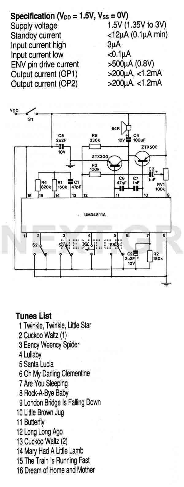
This circuit utilizes a preprogrammed multi-instrument melody generator integrated circuit (IC), which features a 512-note memory capable of producing 16 distinct tunes. The extensive control options allow for the playback of all tunes in a loop or stopping at...
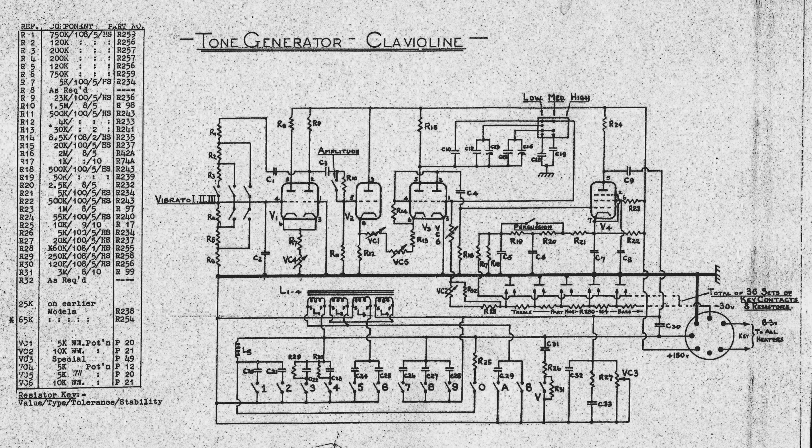
The Clavioline is an early electronic keyboard instrument, similar to the Hammond Solovox. Both instruments are monophonic (single-voiced) and tube-powered, consisting of a keyboard and an amplifier. The first image depicts a restored Clavioline, while the second shows a...
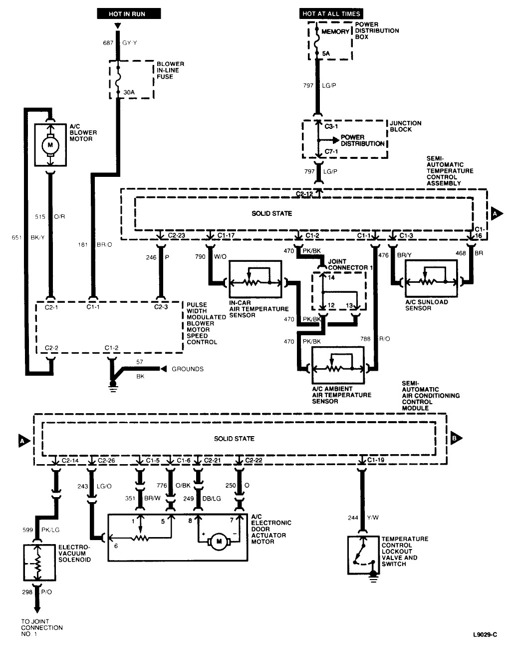
A 1997 Ford Thunderbird experienced a failure of the blower/fan when the air conditioning was activated, accompanied by a snapping sound under the instrument panel. This resulted in no airflow for the air conditioning, heater, or defrost functions. The...

PIC development/testing board. This is a PCB design for a basic PIC16F877 development board. All that is required is a 4 MHz crystal, two 22 pF capacitors, and one 4.7 kΩ resistor. The PIC16F877 development board is designed to facilitate...
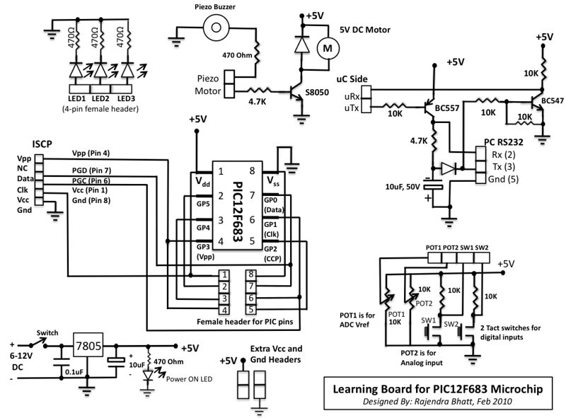
This microcontroller fascinated me a lot because I wanted to see what we can do with an 8-pin microcontroller (out of which 2 pins goes to power supply, so actually just 6-pins are left for I/O). So I thought...
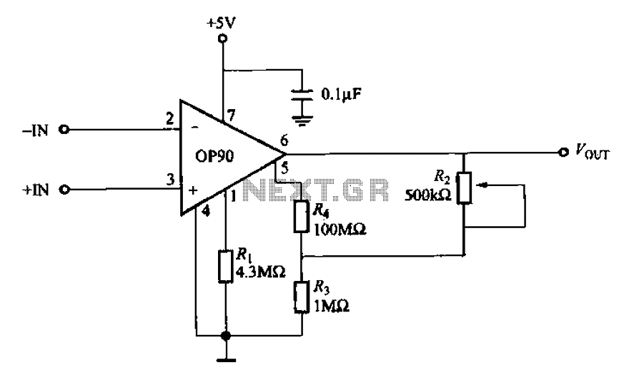
Compared to other operational amplifiers, the OP90 has a significant advantage in low power consumption. Its low power requirements allow for a wide range of power supply voltages (from 1.6V to 18V, and it can also operate with dual...