
pic development testing board using pic16f877 microcontroller

The PIC16F877 development board is designed to facilitate the testing and development of applications using the PIC16F877 microcontroller. The schematic includes essential components to ensure proper functionality and ease of use.
The microcontroller operates with a 4 MHz external crystal oscillator, which provides the necessary clock signal for the device. The two 22 pF capacitors are connected in parallel with the crystal to stabilize the oscillator circuit, ensuring reliable performance. The 4.7 kΩ resistor typically serves as a pull-up resistor for the reset pin, which is crucial for initializing the microcontroller upon power-up.
The PCB layout should accommodate the microcontroller's pin configuration, allowing for easy access to the I/O pins for further development. Additional features may include power supply connections, programming headers, and test points for debugging. The design should prioritize signal integrity and minimize noise, particularly in the oscillator circuit, to enhance the performance of the microcontroller in various applications.
Overall, this development board serves as a fundamental platform for engineers and hobbyists to explore the capabilities of the PIC16F877 microcontroller, enabling the creation of diverse electronic projects.PIC development/testing board Here`s a PCB design for a bare bones PIC16F877 development board. All you need is a 4mhz crystal, two 22pf caps, one 4.7k res.. 🔗 External reference
Related Circuits

The Atmega8 microcontroller from Atmel features numerous digital and analog input/output lines, making it an ideal choice for developing various measurement equipment. It is essential to have the GCC AVR programming environment installed, as outlined in the article "Programming...
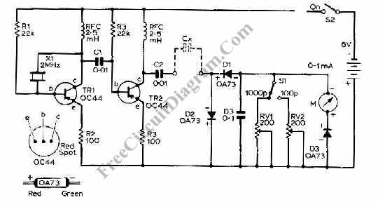
This capacitance meter circuit is similar to previous meter circuits, but it utilizes transistors instead of logic gates. A schematic diagram is provided. The capacitance meter circuit operates by measuring the capacitance of a capacitor through a time-based method. The...
To program an AVR microcontroller using a USB port instead of parallel or serial interfaces, USBasp is the most suitable option. A circuit diagram for USBasp is available. The procedure for burning the hex file includes installing avrdude (WinAVR),...
The character data and command from the microcontroller is transferred serially to a shift register (74HC595), and the parallel output from the shift register is fed to LCD pins. 74HC595 is a high-speed 8-bit serial in, serial or parallel-out...
The LM386 is a widely recognized and effective option for various designs that necessitate a compact audio power amplifier (1-watt) integrated into a single chip. However, the LM386 requires... The LM386 is a low-voltage audio power amplifier that is commonly...
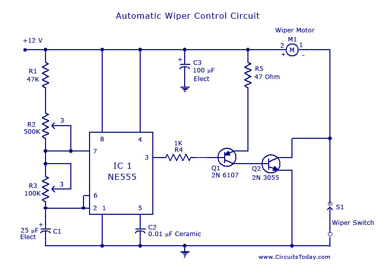
A circuit for car windshield/wiper motor speed control built using an NE 555 IC. This enables intermittent windshield wiper control, which changes the sweep rate to 10 seconds. The circuit utilizes the NE 555 timer IC configured in astable mode...