
Gibson Clavioline Keyboard Instrument (1953)
")
The Clavioline was discovered at an estate sale in 2011, among a collection of antique radios and electronics. Initially priced at $250, a deal was struck for half that amount. Upon inspection, the interior of the Clavioline reveals a speaker, power cord, connecting cable, and the power/amplifier chassis. The keyboard unit is stowed in the back of the cabinet for transport. The instrument is identified only by a plate stating "Made in France," leading to the conclusion that it is a Gibson model manufactured under license in the U.S. The Clavioline functioned intermittently, with several keys producing sound inconsistently. Cleaning and replacing old capacitors is essential for servicing, as is the maintenance of keyswitches and controls. The construction of the Clavioline is relatively straightforward compared to other tube electronics, although a complete restoration requires significant time and effort.
The keyboard unit's cover can be removed to access the tubes, potentiometers, and other electronic components. The pink tubular capacitors, known as "Tiny Chief," are particularly unreliable and should be replaced. The rocker-style control switches, which select tone combinations and vibrato effects, can be cleaned using electronic cleaner. Each keyswitch is a momentary-contact switch that completes the circuit while the key is depressed. Cleaning involves removing the switches in banks and ensuring that the connections are secure. Recapping is a routine practice for tube devices of this era, and the Clavioline's chassis is designed for ease of access to its components.
Capacitors in the Clavioline can be replaced by carefully noting their connections, removing old components, and soldering in new ones. The process requires attention to detail, ensuring that each joint is properly soldered to maintain functionality. While resistors are generally left in place due to their reliability, capacitors must be replaced to ensure the instrument's performance. The Clavioline represents a unique blend of vintage electronic design and musical capability, and its restoration offers insights into the evolution of electronic musical instruments.The Clavioline is an early electronic keyboard instrument, similar to my Hammond Solovox. Both of them are monophonic (single voiced) and tube powered, consisting of a keyboard and an amplifier. The first photo shows my Clavioline after restoration. In the second photo, my son, Peter, is seated at the keyboard. Click the musical icon to hear him playing a brief theme from the well known 1962 song, Telstar. As illustrated, a Clavioline can be used in two ways. First, like a Hammond Solovox, it can be mounted on a piano and played as an adjunct to the piano keyboard. Or, mounted on a tripod, it can be played as a standalone instrument. In the United States, Claviolines were manufactured by the Gibson instrument company. They were also built by JG¶rgensen in Germany and Selmer in England. Since the JG¶rgensen and Selmer instruments differ in construction as well as features, I`ll refer you to the previous links for details about them.
Martin applied for a U. S. patent in 1948 and on August 7, 1951, he was granted patent 2, 563, 477, "Electronic Musical Instrument. " Click the thumbnail to read the patent, with the full description and original drawings: If you`re looking for a layman`s explanation of how a Clavioline works, the patent is not the place to start.
Like most patents, it is written in a dense polyglot of legalese and techno-jargon, aimed at establishing precedence and forestalling infringement. Furthermore, since a patent is drafted to protect ideas and principles in the broadest possible fashion, this one doesn`t literally describe the Clavioline as it was commercially realized.
Still, it`s interesting to see a contemporary expression of Martin`s idea. Interestingly, the last page of Martin`s patent description references an earlier (1939) patent, number 2233258, "Electrical Musical Instrument. " Held by Laurens Hammond and John Hanert, that is the seminal patent for the Hammond Solovox. Some long winter`s evening, I`ll need to sit down and compare the circuitry of these two similar instruments and decide how different they really are.
The Clavioline has more voices and a larger octave range, but presumably more than that was needed to establish that it wasn`t merely a rehash of the earlier Solovox design. Apologies for the low quality of these schematics. If you have a more detailed Gibson service manual, or even clearer copies of these schematics, please contact me.
I also have obtained some Selmer documentation, which is not terribly useful, owing to differences between the American and English instruments. This page from the back of one manual is not identical to the Gibson keyboard schematic, but perhaps it will help you identify a few more items in the blurry Gibson scan: I found this Clavioline at a crowded estate sale in 2011.
The sale was located in a tiny house, whose every room was crammed to the ceiling with shelves for antique radios and other electronics. The fellow in this photo was on the phone, describing every radio in the house to someone on the other end.
I didn`t see any radios or TVs that I wanted, but this little keyboard caught my eye. I recognized the name Clavioline as a monophonic instrument like my Solovox. The price ($250) was too high to tempt me, but I returned the next day and made a deal for half that price. Here is my Clavioline after unloading back at home. Removing the back cover reveals the speaker, power cord, connecting cable, and the power/amplifier chassis.
To transport the Clavioline, you stow the keyboard unit in the back of the cabinet and pop the cover back on. My Clavioline has no identifying information other than the ID plate shown earlier, which says Made in France.
After a little research, I concluded that it`s a Gibson model, sold under license in the United States. Since its components (capacitors and whatnot) are also of U. S. manufacture, I presume the whole thing was manufactured here, not imported as the ID plate suggests. Some time later, I saw photos of an identical model with a sticker on the back of the speaker that said Gibson Ultrasonic.
Perhaps mine once had the same sticker, but it fell off and became lost. The Clavioline worked. . . sort of. I could hear notes from many of its keys, but they were sometimes intermittent. A few of the tone switches had an effect, but others seemed to do nothing, and the vibrato switches were also inoperative. Not to worry, every 60-year old tube device needs service, chiefly in the form of new capacitors. It`s not surprising that the keyswitches and controls need cleaning, too. A Clavioline is not especially complex, compared to other tube electronics. A full restoration will take a number of hours, however, so don`t expect to give yours a complete overhaul in an evening.
By removing a few screws, you can take off the large cover plate on the bottom of the keyboard unit. This exposes the tubes, potentiometers, and other electronic components. The pink tubular components are "Tiny Chief" brand plastic-coated paper capacitors. This type of capacitor is notoriously unreliable and should always be replaced, as explained in my recapping article. Removing the panel exposes the rocker-style control switches, which select tone combinations and vibrato effects.
When a switch is toggled, its blade-shaped upper contact completes a circuit with two or three springy contacts below. As the photo shows, some of those contacts are dark with dirt and oxidation. The control switches have either two or three springy contacts and the circuit is completed when the blade touches them, thus activating the tone filter or other components wired to the contacts.
I`ll clean the control contacts with Q-tips dipped in DeOxit D100L electronic cleaner. Don`t press too hard on the contacts, lest you deform them. After wetting the Q-tip with DeOxit, I gently twirled it on each contact until the discoloration went away. You also need to clean the edge of each blade, of course. The keyswitches are similarly constructed, but they are momentary-contact switches, completing the circuit only while you hold the key down.
To clean them, you`ll need to remove the switches, which come out in three banks, screwed on from behind. The frame has two rows of slots that expose the springy contacts for the keyswitches. The five rubber bumpers protruding from the frame are in line with the black keys. When you release a black key, a small lip on its end hits the lip on the bumper and thus prevents the key from rising up too far.
(The front edges of the white keys are similarly held when at rest, by the edge of the keyboard front panel that we removed earlier. ) Each keyswitch has two springy contacts below, and every keyswitch blade is connected to chassis ground.
Depressing the key grounds both contacts, with a very slight delay between touching the first and second contact. This ensures a clean attack for the note, without any electrical pops or clicks. As with the control switch contacts, I dipped a Q-tip in DeOxit and twirled it on each set of contacts to clean them.
After finishing the first bank, I reinstalled it and proceeded to the second bank. The lip on one of the black keyswitches had broken and become lost. I cut a little piece from a popsicle stick and glued it on with epoxy. Not as beautiful as an original key, but now it works exactly the same! The next photo shows an important detail. Before removing the third bank of keys, you must unsolder this wire, which connects every keyswitch to chassis ground. Solder this wire back in place when you reinstall the bank; a secure ground connection is critical for keyboard operation.
Recapping is a routine practice for every tube device from this era. Since this Clavioline article is likely to be read by non-radio folks, I`ll describe the basic process in more detail than usual. This photo shows the keyboard chassis and the tools that I`ll use: a soldering iron, wire cutter, needlenose pliers, bulb solder sucker, and a couple of steel tweezers.
The Clavioline chassis is easy to work on, compared to most radios and TVs of the era. Components are neatly arranged on phenolic terminal boards and their connections are readily accessible, rather than buried under other components and wires. We`ll begin by replacing the capacitor shown in the next photo. It`s likely a replacement, installed during past service. These white tubular caps were no better than the pink Tiny Chiefs, so I`ll replace it even though it may be a few years newer.
The old capacitor`s value is. 025 mfd. The schematic calls for. 020 mfd. I`ll replace it with the modern value, . 022 mfd. A difference of. 002 from the specified value will not matter. Most old components were manufactured within a tolerance of 20% above or below the nominal value, so a difference of. 002, or 2%, is well within the needed value range. I carefully note where the capacitor is connected and then snip each end. Then I can melt the solder on each terminal and remove the wire stubs with a plier. This is easier than trying to work the wire loose from the terminal while the capacitor is still connected, which can damage the terminal if you yank too hard.
The new capacitor is smaller than the original and it will easily fit the space. I snip its ends and bend them to fit neatly around the terminals. If a terminal has holes (these don`t), you can run the new capacitor`s lead through the hole and bend it around the terminal a bit, before snipping to length and crimping. Next, I crimp the pre-formed wire ends onto the terminals and secure them with new solder. Always heat the joint first and then apply the solder to the heated joint rather than to the hot iron.
This distributes melted solder evenly throughout the joint. It is very bad practice to melt solder on the iron and let that drip onto a cold joint. Sometimes, when a delicate component is connected to a terminal, I`ll temporarily clip a metal tweezer onto that component`s lead, to act as a heat sink and prevent overheating damage. That`s not necessary in this case, since I`m working quickly and heating the joint only long enough to flow the solder into and around the joint.
Replacing the remaining capacitors was simply more of the same. The process looks laborious when you document every step, but with practice, you`ll be able to replace a capacitor in only a minute or two. In a typical radio or TV restoration, I leave all or most of the original resistors in place. Resistors are more reliable than capacitors and in many cases their precise value isn`t critical in the first place.
🔗 External reference
Related Circuits

The Wildcard requires a minimum of 8 volts on the V+Raw power rail, which must not exceed 26 volts. When using the Docking Panel or Power Dock, the V+Raw rail is automatically connected. If not using a dock, manual...
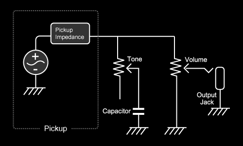
Magnets with a long coil wound around them transform the vibrations of strings into an electric signal. This refers specifically to "magnetic" pickups, not "piezo" pickups. In configurations with 1 Volume/2 Tone or 1 Volume/1 Tone, the hot wires...
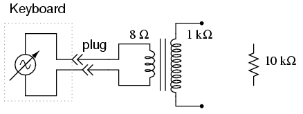
An electronic musical keyboard serves as a source of variable-frequency AC voltage signals. It is not necessary to purchase an expensive keyboard; a model with at least a few dozen voice selections (such as piano, flute, harp, etc.) is...
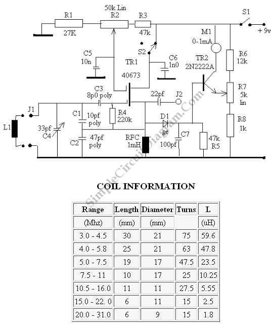
This is a grid dip oscillator (GDO) circuit developed by Luigi Falcone. The circuit uses seven plug-in coils that cover the frequency range of 3.0 to 30 MHz. It can be connected to a frequency meter through the coaxial...
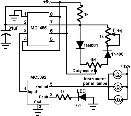
This circuit utilizes an MC3392 low-side protected switch in conjunction with an MC1455 timing circuit to create a dimmer control for automotive instrumentation panel lamps. The brightness of incandescent lamps is adjustable through Pulse Width Modulation (PWM) applied to...
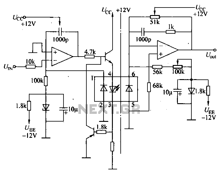
A universal optocoupler is utilized in electrocardiographs, as illustrated in Figure 5-29. Pin connections must be made carefully: the positive terminal should be connected to pin O, while the negative terminal should connect to the other pin. The control...