
Schematic Diagram 300W Power Amplifier For Subwoofer
The 300W amplifier circuit is designed for high performance in audio amplification applications, particularly suited for driving subwoofers. The use of a 4.7µF bipolar capacitor at the input stage ensures that the amplifier maintains a compact design while providing sufficient capacitance to handle low-frequency signals effectively. The choice of a polyester capacitor as an alternative allows for flexibility based on component availability and personal preference, while still ensuring that the amplifier can achieve a -3dB frequency response suitable for subwoofer applications.
The amplifier's capability to deliver over 150W into an 8-ohm load, and up to 250W with ±70V supply voltages, demonstrates its robustness for continuous operation. The design's reliance on additional transistors is minimal, only necessary for applications requiring 4-ohm loads, which speaks to the circuit’s efficiency and reliability in various audio setups.
The output stage, featuring MJL4281A and MJL4302A transistors, is a critical component of the amplifier's performance. While these transistors may not always be readily available, the recommended alternatives—MJL3281/MJL1302 or MJL21193/MJL21194—provide similar performance characteristics, ensuring that builders can source components without compromising the circuit's integrity.
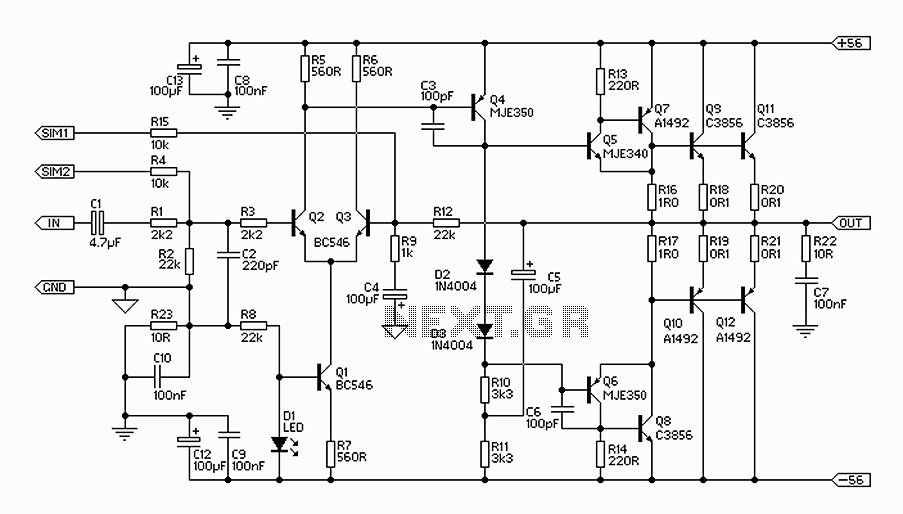
Operating in a "pure" Class-B configuration, the amplifier is expected to exhibit higher distortion at high frequencies, which may limit its application in high-fidelity audio systems. However, the significant negative feedback implemented at lower frequencies helps to maintain distortion levels around 0.04% up to 1kHz, making it suitable for bass-heavy audio applications. Observations from initial testing indicate a lack of audible artifacts at high frequencies, reinforcing the amplifier's performance reliability for subwoofer applications. Overall, this circuit design presents a balanced approach to audio amplification, prioritizing both power output and sound quality within its operational parameters.The 300W Amplifier circuit is shown it is a reasonably conventional design. Connections are provided for the Internal SIM, and filtering is provided for RF protection (R1, C2). The input is via a 4. 7uF bipolar cap, as this provides lots of capacitance in a small size. Because of the impedance, little or no degradation of sound will be apparent. A polyester cap may be used if you prefer - 1uF with the nominal 22k input impedance will give a -3dB frequency of 7. 2Hz, which is quite low enough for any sub. Continuous power into 8 ohms is typically over 150W (250W for ±70V supplies), and it can be used without additional transistors at full power into an 8 ohm load all day, every day.
The additional transistors are only needed if you want to do the same thing into 4 ohms at maximum supply voltage Although I have shown MJL4281A and MJL4302A output transistors, because they are new most constructors will find that these are not as easy to get as they should be. The alternatives are MJL3281/ MJL1302 or MJL21193/ MJL21194. Because this amplifier circuit operates in "pure" Class-B (something of a contradiction of terms, I think), the high frequency distortion will be relatively high, and is probably unsuited to high power hi-fi.
At the low frequency end of the spectrum, there is lots of negative feedback, and distortion is actually rather good, at about 0. 04% up to 1kHz. My initial tests and reports from others indicate that there are no audible artefacts at high frequencies, but the recommendation remains.
🔗 External reference
Related Circuits
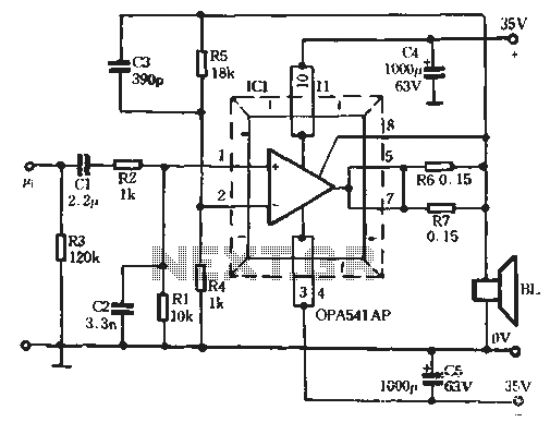
The Burr-Brown OPA541 chip is a power amplifier capable of operating with a maximum power supply voltage of 40V, delivering a continuous output current of up to 5A. The output current can be adjusted using an external resistor to...
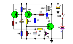
Simple circuit, no ICs required, 12V battery operation. This circuit was requested by several correspondents. Its purpose was to obtain more power than the standard configurations allow. This circuit design utilizes a 12V battery as the primary power source and...
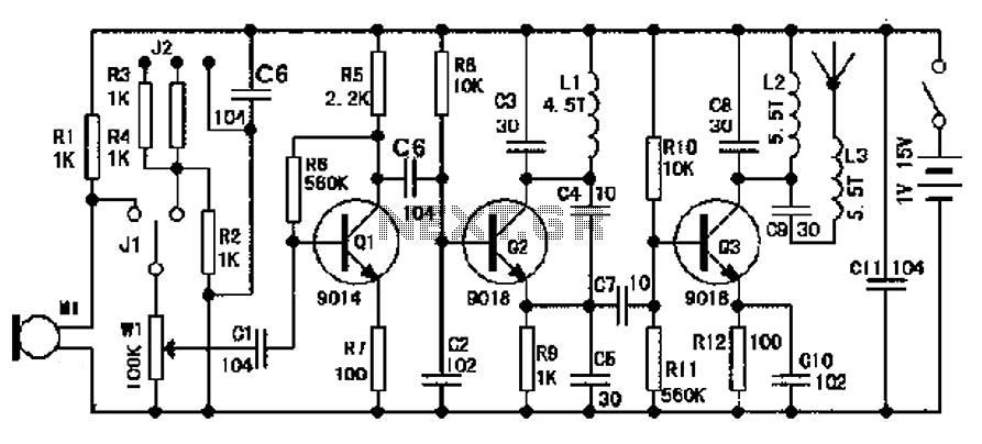
The design of an FM radio transmission frequency band enables compatibility with any FM radio receiver, allowing the high-frequency signal to be transmitted and restored from an audio signal. This technology serves various applications. Applications of a wireless microphone...
The gain of the low-cost IC is internally fixed at no less than 34 dB (50 times). A unique input stage allows input signals to be referenced to ground. The output is automatically self-centering to one-half the supply voltage...
This circuit is designed to indicate when a plant requires watering. An LED blinks at a low frequency when the soil in the flower pot is excessively dry, turning off as the moisture level rises. The sensitivity of the...
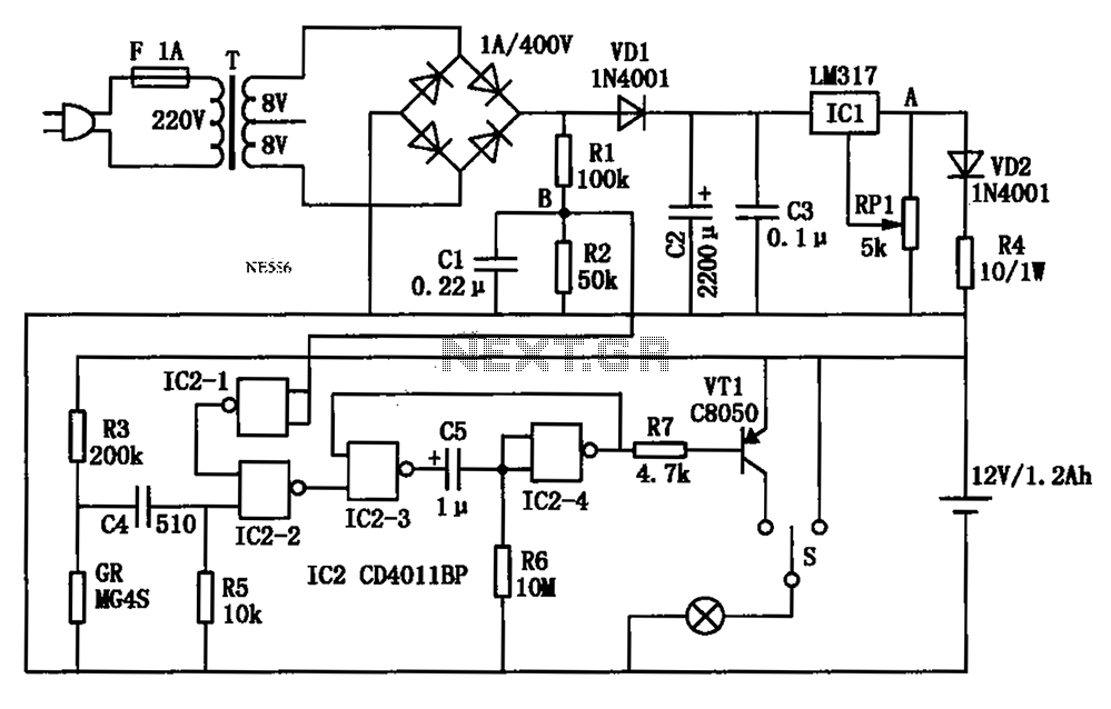
An automatic multipurpose emergency lights circuit is presented. Typically, emergency lights are connected to the mains for standby when fully charged. In the event of a sudden power failure, the ambient light transitions from strong to weak, indicating a...