
DC-DC converter to step up input voltage
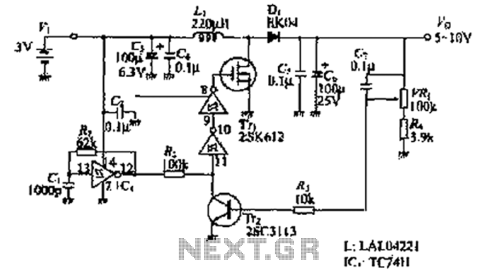
This circuit operates as a basic step-up converter, utilizing a TL496 integrated circuit, a coil (inductor), and capacitors to achieve voltage amplification. The TL496 functions as an oscillator, generating a square wave signal that drives the inductor (L1). When a voltage is applied to the inductor, it stores energy in its magnetic field. As the oscillation occurs, this stored energy is released into the output circuit, resulting in a higher voltage than the input.
The choice of inductor significantly affects performance; variations in coil design, such as the number of turns and wire gauge, can lead to different output voltages and efficiencies. The circuit's oscillation frequency is determined by the resistor (R1) and capacitor (C1) values, which can be adjusted to optimize performance based on the specific inductor used.
Capacitor C2 plays a crucial role in smoothing the output voltage, and its voltage rating must exceed the expected output. Using a capacitor with a higher capacitance value can reduce ripple voltage, leading to a more stable output.
To initiate the operation of the circuit, especially when using lower input voltages, it may be necessary to temporarily provide an external voltage to the oscillator. This ensures that the circuit can start generating the necessary high frequency for the step-up operation.
The circuit's design allows for experimentation, making it suitable for various applications, including powering devices from lower voltage sources or charging batteries. Adjustments to component values and configurations can lead to improved efficiency and performance, making this a versatile project for electronics enthusiasts.This is a simple circuit which outputs a voltage which is more than the input. This could be used to power 12v or 9v devices from a 6v system, or even 6v devices from a 1. 5v battery (see below). This circuit uses bog standard parts, without requiring a magical "do-it-all" IC. You can make an ultra simple 1. 5v to 9v regulated stepup converter by us ing a TL496 IC, a coil and a capacitor, but that`s not so much fun if you want to experiment. I`ve already built a TL496 based circuit so I started doing web searches for something that I could make that would allow more fiddling and a wider range of applications. The only unusual component in this circuit is the coil (L1). I am not going to give you instructions on how to wind "the" coil because so many different types work with this circuit.
Even a small DC motor works! These are the coils I have tried so far: The 60 turn coil gave the highest output voltage but the current draw without any load was already 40mA, probably because its DC resistance is very low. The motor and hookup wire coil gave reasonable performance. The solenoid seemed to give the best overall performance. The values shown for R1 and C1 will cause oscillation at about 40KHz. You should experiment with these too as different coils may perform differently at different frequencies.
When I decreased R1 to 130k the frequency increased to about 180KHz and the output voltage increased by a few more volts. Make sure C2 is rated for the output voltage. I used a 47uF 50v electro because it`s what I happened to have lying around. A higher value may give better performance with less ripple on the output. The first setup of this circuit used the solenoid and a 9v battery. The output was around 41v with no load. With the 60 turn coil, it exceeded 80v! (With a 50v rated capacitor for C2 I didn`t leave this running for long. ) What I found more interesting was using a single AA cell (1. 5v). You may get mixed results because the 74C14/40106 schmitt trigger inverter may not be able to work at voltages this low.
One trick you can do is to power the 74C14/40106 from the output voltage. The only problem is that the circuit needs a kick start, since it can`t step up voltage until the oscillator is running. I found that a 10k resistor across the diode (normally 0. 6v drop) provided sufficient voltage to get the oscillator started, without affecting the output too much.
Startup is not instantaneous because the output capacitor needs to charge. Another way to get it started is to temporarily connect a 3-9v battery in series with a 10k resistor to the supply rails of the 74C14/40106. This method is more reliable but it`s not so practical since you need another power source. However, if you are using this circuit to do something like charge a 6v battery from a 1. 5v solar cell, then you can simply power the 74C14/40106 from the battery. There is none. The output voltage will dip as you load it more. While you can use a series regulator such as a 7812 or 7805 on the output (take care not to exceed their maximum input voltage) I`m guessing that pulse width modulation (PWM) of the 40KHz square wave would be a more efficient method of regulation.
I haven`t looked into this yet as it adds more complexity to the circuit, requiring some sort of feedback to vary the duty cycle. A PIC or Atmel with an A/D converter and a spare output, plus some fancy programming, would probably do the trick.
This is a basic circuit only and it can be improved in many ways. Building it on a breadboard makes it easy to fiddle with values of components. Make sure you don`t accidentally exceed the ratings of any components if you manage to find a variation that steps up 12v by 10 times! Note added September 2009 - I get a lot of emails from people asking for detailed help with modifying this circuit.
I`m not an engineer - my knowledge of electronics is elementary to intermediate. In addition, I haven`t 🔗 External reference
Related Circuits
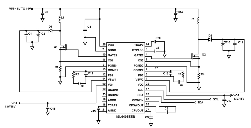
The ISL6405 is a highly integrated voltage regulator and interface integrated circuit (IC) designed to supply power and control signals from advanced satellite set-top box (STB) modules to the low noise blocks (LNBs) of two antenna ports. This device...
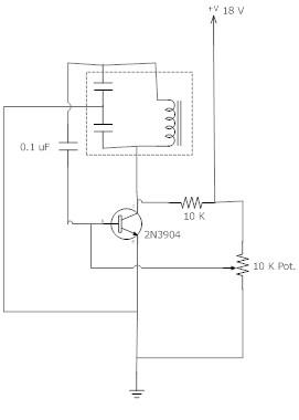
The frequency remains stable as the voltage decreases. It is referred to as the "backwards JT" because it operates optimally with a bifilar coil and a single transistor. With a modification to the circuit, it is possible to deplete...
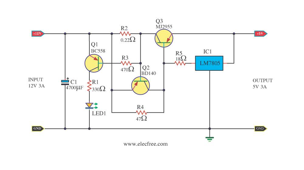
Today, a 12V to 5V 3A DC converter step-down regulator circuit has been presented. Sometimes, individuals have a 12V 3A power supply but require a 5V 3A output for digital circuits. This circuit fulfills that requirement by utilizing standard...
The design of the power supply circuit diagram utilizes an oscillator circuit from the 74HC series of CMOS logic circuits, with a MOSFET as the switching device. This configuration allows for the development of small-scale power supplies suitable for...
In this circuit, the 555 timer is utilized in an innovative manner as a voltage-controlled switch. The widely used NE555 can perform effectively in various applications. The 555 timer, a versatile integrated circuit, is commonly employed in timer, delay, pulse...
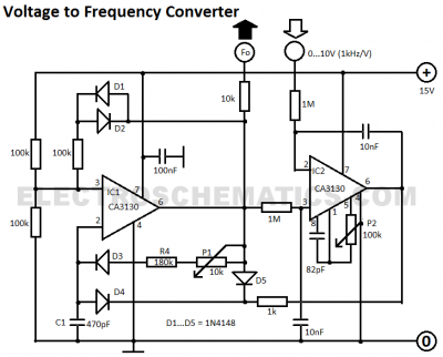
This voltage-to-frequency converter circuit features a voltage-controlled oscillator with a small deviation of 0.5%. The integrated circuit IC1 operates as a multivibrator. The voltage-to-frequency converter circuit is designed to convert an input voltage into a corresponding frequency output. The core...
Warning: include(partials/cookie-banner.php): Failed to open stream: Permission denied in /var/www/html/nextgr/view-circuit.php on line 713
Warning: include(): Failed opening 'partials/cookie-banner.php' for inclusion (include_path='.:/usr/share/php') in /var/www/html/nextgr/view-circuit.php on line 713