
Day / Night Electronic Thermostat

A light level sensor, utilizing an ORP12 light-dependent resistor (LDR1), is integrated into a straightforward circuit to toggle between day and night settings. The circuit triggers when the light level falls below a threshold set by a variable resistor (VR1). In low light conditions, a transistor (TR1) activates a relay (RLA1). An optional LED (LED1) can serve as an indicator for daylight mode, with a current-limiting resistor (R6). A diode (D2) is included to protect against back EMF generated when the relay is deactivated. When the circuit is triggered, a second transistor (TR2) is energized, supplying additional voltage to TR1 to introduce hysteresis, preventing rapid switching due to fluctuating light levels.
The thermostat operates on principles similar to previous designs, with a key distinction: during darkness, RLA1 remains de-energized, short-circuiting variable resistor (VR3) through the relay contacts. The resistance in the circuit during darkness consists of resistors R7 and VR2, providing values between 91k and 113k, which correspond to switching temperatures from 0°C to 27°C. When light levels increase and activate RLA1, VR3 is added in series with R7 and VR2, raising the resistance and the switching temperature by up to 22k. The output field-effect transistor (TR2) controls a second relay (RLA2) to switch the connected load, which in this case is the heating elements. An additional indicator (LED2) signals when the target temperature is reached and turns off when the relay is engaged. Diode D2 is again utilized to protect TR2. The outputs from RLA2 can be used to switch various loads, and the integrated circuit (IC3) is mounted on a cable approximately one foot long for optimal positioning. Care should be taken, as the TC622 IC is sensitive to long cable lengths. To mitigate ripple issues, a capacitor (C5) is placed across the power pins of IC3 to ensure stable operation despite the extended wiring.This design was created at the request of my father. It is designed to operate a 240V a. c. heater, in his Orchid box, to maintain a higher temperature during daylight hours than darkness. Regulator - This is a very simple regulator used here to obtain a stabilised 12V supply. The 78M12 regulator used is rated for 0. 5A, but any 78 12 regulator coul d be used if it provides sufficient current for your circuit. I had problems with the circuit due to ripple on the output, from the mains supply, and I fitted C4 to remove it. An option is to fit LED3 to indicate power with R9 acting as a current limiter. Light Level Sensor - An ORP12 (LDR1) light dependant resistor is connected to a very simple circuit to swap between day an night settings.
The unit will trigger once the light level drops below a certain level set by VR1. When dark enough, TR1 will cause the relay (RLA1) to operate. Optionally LED1 can be fitted to indicator daylight mode with R6 acting as a current limiter. D2 is fitted to prevent the back EMF generated when RLA1 is switched off from destroying TR1. When the unit triggers, TR2 is energised and provides an additional voltage to TR1. This introduces hysteresis in to the unit and stops it switching back and fore if the light level fluctuates around the trip point. Thermostat - The basic principle of this unit is the same as my original thermostat designs. The main difference is that during darkness RLA1 will not be energised and therefore VR3 will be short circuited by the relay contacts.
The resistance in the circuit during darkness will be R7 and VR2 and therefore between 91k and 113k, giving switching temperatures between 0 °C and 27 °C. When the light level rises causing RLA1 to operate the value of VR3 will be in series with R7 and VR2, giving an increase of up to 22k resistance and 27 °C switching temperature.
The output FET (TR2) in this case drives RLA2 to switch whatever load is connected to the contacts. The second indicator (LED2) acts as a temperature reached indicator and is extinguished when the relay is operated. D2 is again fitted to protect TR2. The outputs of RLA2 can be used to switch almost anything, but in this case will connect to the heating elements.
I actually mounted IC3 on the end of a cable (approx. 1` long) to allow positioning where required. You need to be careful, because the TC622 doesn`t seem to like long cables. Because of the ripple problem above, I fitted C5 across the power pins of IC3 to help prevent any problems due to the long wires. 🔗 External reference
Related Circuits
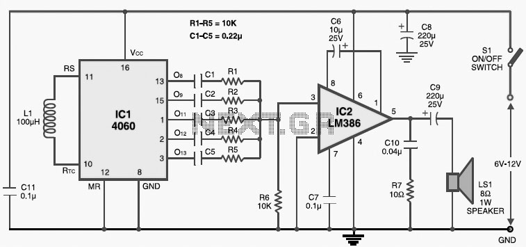
This multitone electronic siren is useful for burglar alarms, reverse horns, etc. It produces five different audio tones and is much more attention-grabbing than a single-tone siren. The circuit is built around the popular CMOS oscillator-divider IC 4060 and...
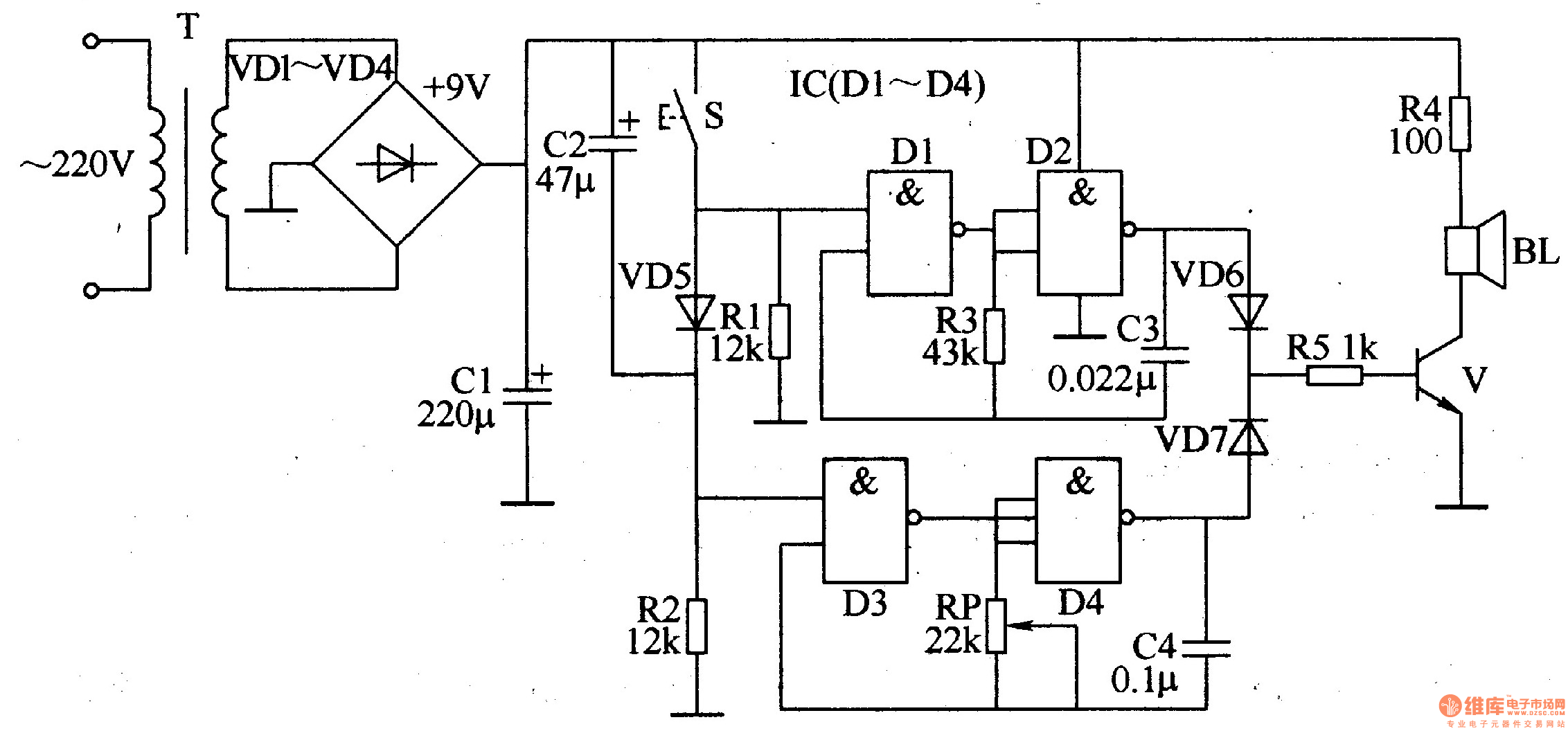
The ding-dong electronic doorbell circuit consists of a power supply circuit, a trigger control circuit, and an audio oscillator output circuit. The power supply circuit includes a power transformer (T), rectifier diodes (VD1-VD4), and a filter capacitor (C1). The...

This smoke detector electronic project is designed using the LM1801 and common electronic components. The smoke detector circuit diagram does not utilize ionization detection, gas sensors, or optocouplers; instead, it employs two photoresistors (LDRs) and an LED. The circuit...
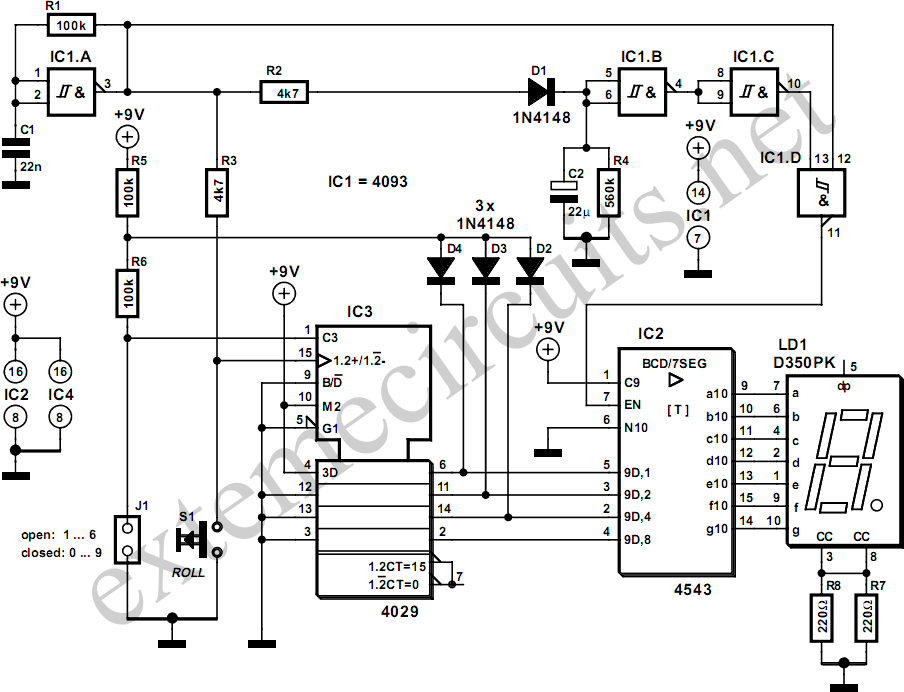
The simplicity of a traditional die makes it exceptionally difficult to create a fully equivalent electronic version, primarily because an electronic version necessitates a power supply and a collection of electronic components that occupy a significantly larger volume than...
The SL517 is designed as an audio, RF, or infrared decoder circuit suitable for electronic toy applications. The internal circuitry consists of an analog amplifier, a frequency divider, a bistable circuit, and a driver. It utilizes CMOS technology, has...
This circuit is a modification of the Hartley oscillator, incorporating several additional components. It utilizes a small audio transformer. The modified Hartley oscillator circuit enhances the traditional design by integrating extra components that can improve performance characteristics such as stability,...