
Ding-dong electronic doorbell
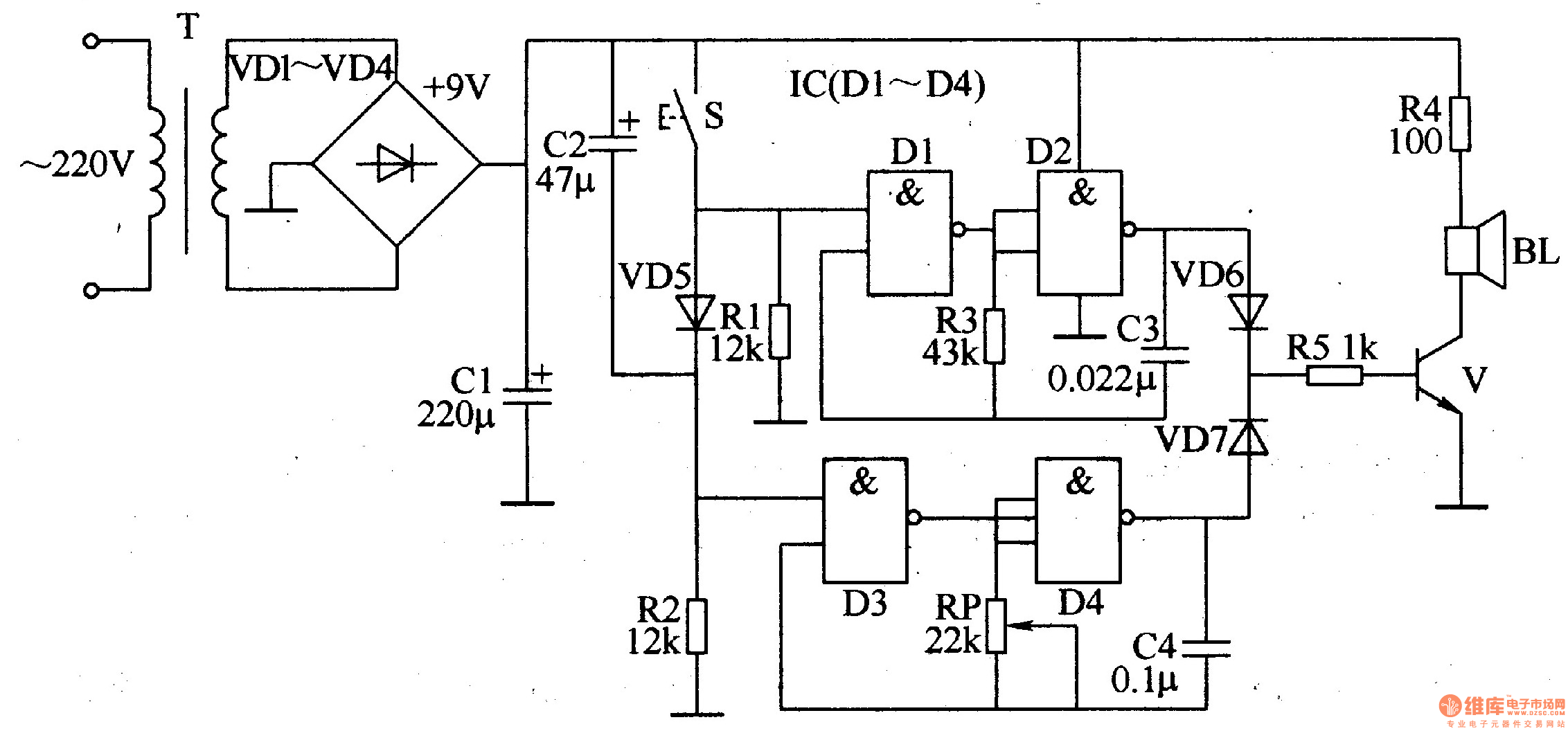
The electronic doorbell circuit operates through several interconnected modules that ensure the functionality of the doorbell system. The power supply circuit is crucial for converting the mains voltage to a lower, usable voltage for the other components. The power transformer (T) steps down the voltage, while the rectifier diodes (VD1-VD4) convert the AC voltage to DC. The filter capacitor (C1) smooths the rectified voltage to provide a stable power source for the circuit.
The trigger control circuit is activated when the doorbell button is pressed. This circuit includes a control circuit (S) that manages the flow of current to the audio oscillator. The diode (VD5) protects the circuit from reverse polarity, while capacitor (C2) and resistors (R1, R2) help in shaping the signal and ensuring proper operation of the trigger circuit.
The audio oscillators are responsible for generating the sound output of the doorbell. Audio oscillator A utilizes diodes (D1, D2) within a NAND gate IC (D1-D4) along with resistor (R3) and capacitor (C3) to create a specific frequency tone. Audio oscillator B, on the other hand, employs diodes (D3, D4) within the same IC, a potentiometer (RP) for volume control, and capacitor (C4) to stabilize the oscillation frequency.
Finally, the audio output circuit converts the oscillating signals into audible sound. This section consists of resistors (R4, R5) which limit the current to the audio output, diodes (VD6, VD7) that provide signal protection, and a transistor (V) that amplifies the audio signal. The speaker (BL) then produces the sound that alerts the user when someone presses the doorbell.
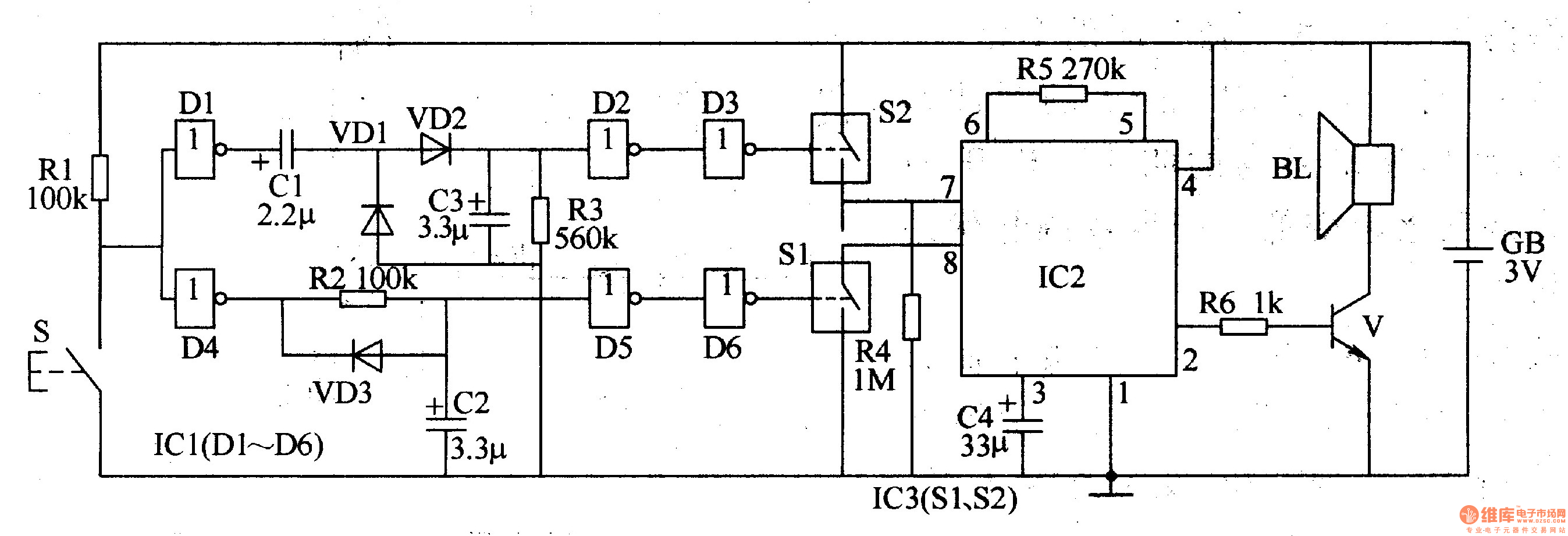
Overall, the integration of these components allows for a reliable and efficient electronic doorbell system, providing both functionality and user-friendly operation.The ding-dong electronic doorbell circuit is composed of the power supply circuit, trigger control circuit, audio oscillator output circuit, and it is shown in Figure 3-125. Power supply circuit is composed of the power transformer T, rectifier diodes VDl-VD4 and filter capacitor Cl.
Trigger control circuit is composed of the doorbell button, cont rol circuit S, diode VD5, capacitor C2 and resistors Rl, R2. Audio oscillator A consists of the Dl, D2 which are inside of four NAND gate IC (Dl-D4) and resistor R3, capacitor C3. Audio oscillator B consists of the D3, D4 which are inside of IC and potentiometer RP, capacitor C4. Audio output circuit consists of resistors R4, R5, diodes VD6, VD7, transistor V, and the speaker BL.
🔗 External reference
Related Circuits
Voltage inverter circuit design electronic project using few electronic components The voltage inverter circuit is a fundamental electronic project that converts direct current (DC) to alternating current (AC). This circuit is particularly useful in applications where AC voltage is required...
The circuit functions as a random number generator, producing numbers from 1 to 6. It features a line of LEDs, each corresponding to a number in the range of 1 to 6. When the push button S1 is pressed...
The automotive electronic code lock circuit is depicted above. IC1 is a dedicated lock for the integrated circuit 5G058, with its designated pins connecting an external key switch to the power supply. There are six valid input keys, and...
The two-tone electronic doorbell circuit comprises a trigger control circuit and a doorbell generating circuit, as illustrated in Figure 3-108. The trigger control circuit includes a doorbell button (S), resistors (R1-R3), electrical components (C1-C3), diodes (VD1-VD3), six NOT gate...
Design and implementation of a TC237 CCD camera. The TC237 CCD camera is a sophisticated imaging device that utilizes a Charge-Coupled Device (CCD) sensor for capturing high-quality images. The design process involves several key components, including the optical system, electronic...
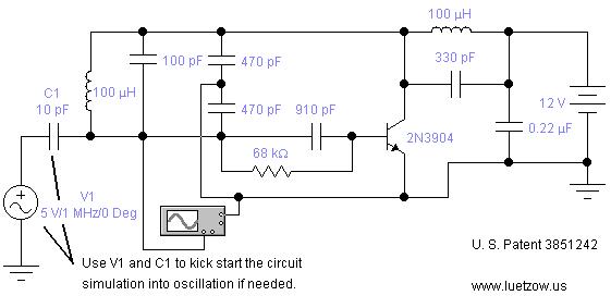
The oscillator circuits presented on this page are derived from expired or non-maintained U.S. Patents. All circuits are formatted for "Electronic Workbench 5.12" or "Multisim 7" circuit simulation software. A note regarding SPICE simulation of electronic oscillator circuits: all...
Warning: include(partials/cookie-banner.php): Failed to open stream: Permission denied in /var/www/html/nextgr/view-circuit.php on line 713
Warning: include(): Failed opening 'partials/cookie-banner.php' for inclusion (include_path='.:/usr/share/php') in /var/www/html/nextgr/view-circuit.php on line 713