
Electronic Die

The electronic die circuit is designed to mimic the functionality and appearance of a traditional die while integrating modern electronic components for enhanced features. The core of the circuit is the oscillator (IC1a), which generates a clock signal that drives the counter (IC3) and controls the display's pulsing behavior. The use of a jumper to switch the counting range from 1-6 to 0-9 provides flexibility in operation, allowing the user to customize the die's behavior.
The standby function is particularly noteworthy, as it conserves battery life by disabling the display after a brief period of inactivity. This is achieved through a combination of capacitive charging and discharging, which ensures that the display is only active when needed. The use of a common-cathode configuration for the display segments simplifies the circuit and reduces component count, although care must be taken to manage brightness consistency across different displayed values.
In summary, this electronic die circuit combines simplicity with functionality, providing an engaging alternative to traditional dice. Its design allows for easy assembly using either standard or SMD components, making it accessible to a wide range of builders and hobbyists. The thoughtful integration of features such as adjustable counting range, energy-efficient display operation, and standby mode enhance the usability and longevity of the device, making it a practical addition to any electronic project.The simplicity of a traditional die makes it exceptionally difficult to create a fully equivalent electronic version, if only because an electronic version requires a power supply and a collection of electronic components that occupy a much larger volume than a normal die. This article describes an electronic die that can be built using normal com ponents or SMDs as desired, and which comes very close to having the same format as a traditional die in the latter case. Despite its simplicity, this electronic die incorporates several interesting features. For instance, the range of spots` can be increased from 1 6 to 0 9 using a jumper, and it has standby function that disables the display approximately 8 seconds after the die has been thrown`, in order to save energy.
The electronic die also uses energy efficiently by driving the display in pulsed mode. As a result of the latter two features, the current consumption of the circuit is approximately 25 mA in use and 12 mA in standby. This means that it can easily be powered by a 9-V battery. The circuit consists of the following parts: a free-running oscillator (IC1a), additional logic for driving the display (IC1c & IC1d), a timer (IC1b), a counter (IC3) and a display decoder (IC2).
The oscillator is very simple. Its frequency, which is determined by R1 and C1, is approximately 225 Hz, with a duty cycle of around 50 60 percent. The signal from the oscillator acts as a clock signal for the counter (via R2) and a blanking signal for the display decoder (via IC1d).
However, the counter will not count as long as the throw` switch (S1) remains closed, since the clock input of IC3 is grounded by S1. The blanking input of the display decoder is driven by a pulse waveform, so the display is in principle illuminated only around 50 percent of the time, but it appears to be constantly illuminated due to the high clock frequency.
The standby mode works as follows. As long as there is a signal on the clock input of the counter (S1 pressed), the output of gate IC1b is low and the display is enabled. If S1 is released, the counter stops and a number will be shown on the display. However, the clock pulses will have charged C2 via D1, and C2 will slowly discharge via R4. After approximately 8 seconds, the output of gate IC1b will go high, causing the display to be blanked.
The design of the counter is relatively simple. It is wired as an up counter by connecting the U/D pin to VCC. The preset inputs (pins 4, 12, 13 and 3) are configured to binary 0001`, and the counter normally has a counting range of 0 9 (pin 9 connected to ground). Diodes D2, D3 and D4, in combination with resistor R5, act as a logic AND gate, so if the value of the counter is greater than 6, the preset value of 1 is latched into the counter and it starts to count again from 1 to 6.
This only happens if jumper J1 is open. If it is closed, the preset pulse on PREN is suppressed and the counter range is 0 9. The A, B, C and D inputs of the decoder IC (IC2) are driven directly by the counter. The series resistors normally used for the individual segments of the display are instead placed in the common-cathode lead (R7 & R8). This has the advantage of allowing the number of resistors to be reduced, although it has the drawback that the brightness of the display depends on the displayed number.
If the segment current is sufficiently large, (light) saturation occurs and this brightness variation is no longer noticeable. The Blank input (BL) controls whether the display is enabled. If you choose to build this circuit using SMD technology, that will not affect the schematic diagram, but it will naturally affect the choice of components.
In this case, SMD components must be used for the resistors and C1, the diodes must be replaced by BAS32 types, and BT versions of ICs IC1 IC3 must be used instead of conventional types. An SMD version of C2 was not used in the prototype, since SMD electrolytic capacitors are expensive, and normally they are only sold in lots of 10, just like other passive components.
It is also recommended to use a socket for the display of the SMD version of the electronic die, to allow the space under the display to also be used and the dimensions of the circuit board to be further reduced. Any desired DC power source providing a voltage of 5 to 15 V can be used as a power supply. Due to the low current consumption of the circuit, a 9-V battery will last quite a long time. 🔗 External reference
Related Circuits
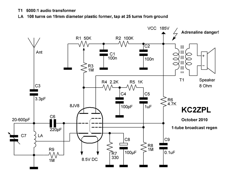
KC2ZPL Web Design, electronics, HAM radio, CW, homebrew construction, general electronics, high voltage, experimenter's web page. The KC2ZPL web page serves as a comprehensive resource for individuals interested in various aspects of electronics and amateur radio (HAM radio). It covers...
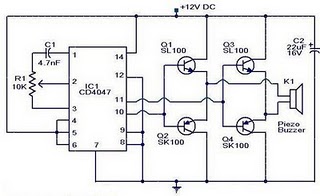
The circuit operates on the principle that insects, such as mosquitoes, can be repelled using sound frequencies in the ultrasonic range (above 20 kHz). It utilizes a Phase-Locked Loop (PLL) integrated circuit, specifically the CMOS 4047, configured as an...
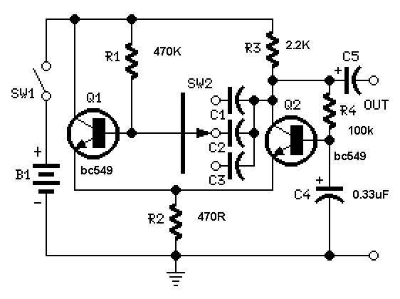
A useful feature of this circuit is that the frequency can be changed by modifying the capacitor value. A switch can be added to select between various frequencies. This circuit utilizes a capacitor in conjunction with an oscillator to determine...
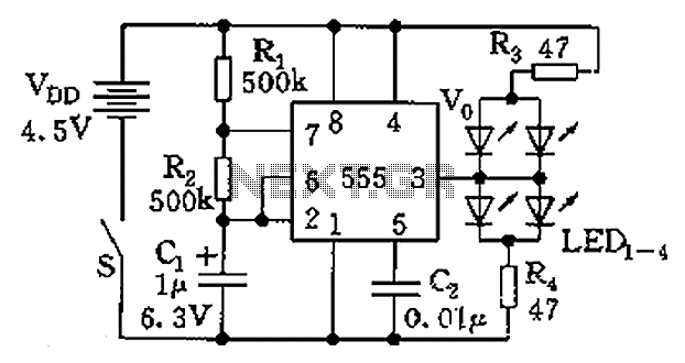
The circuit consists of a 555 timer and a light-emitting diode (LED) array. The 555 timer, along with resistors R1, R2, and capacitor C1, forms an astable multivibrator configuration. The oscillation frequency is calculated using the formula f =...
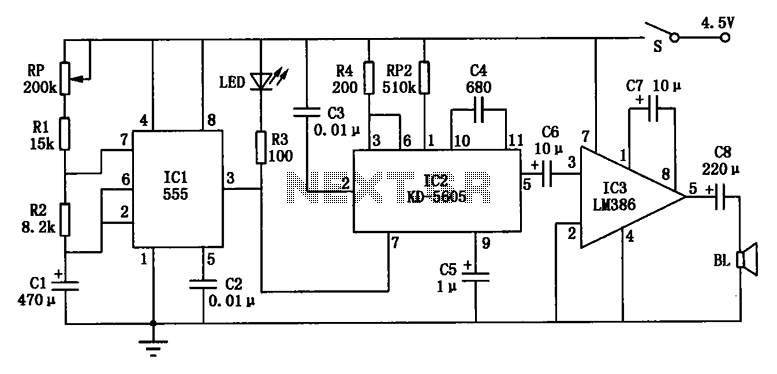
The electronic circuit depicted in Figure cat features the NE555 time base integrated circuit (IC1), along with a potentiometer (RP), resistors (R1 and R2), and a capacitor (C1) that collectively form a time control circuit for regulating intervals. The...
This document discusses the power electronics required for an electrical discharge machining (EDM) machine. The fundamental mechanism of EDM involves a controlled spark between the electrode and the workpiece. The electronic design must generate the necessary waveforms to induce...