
DC 12V Battery Charger Circuit Schematic
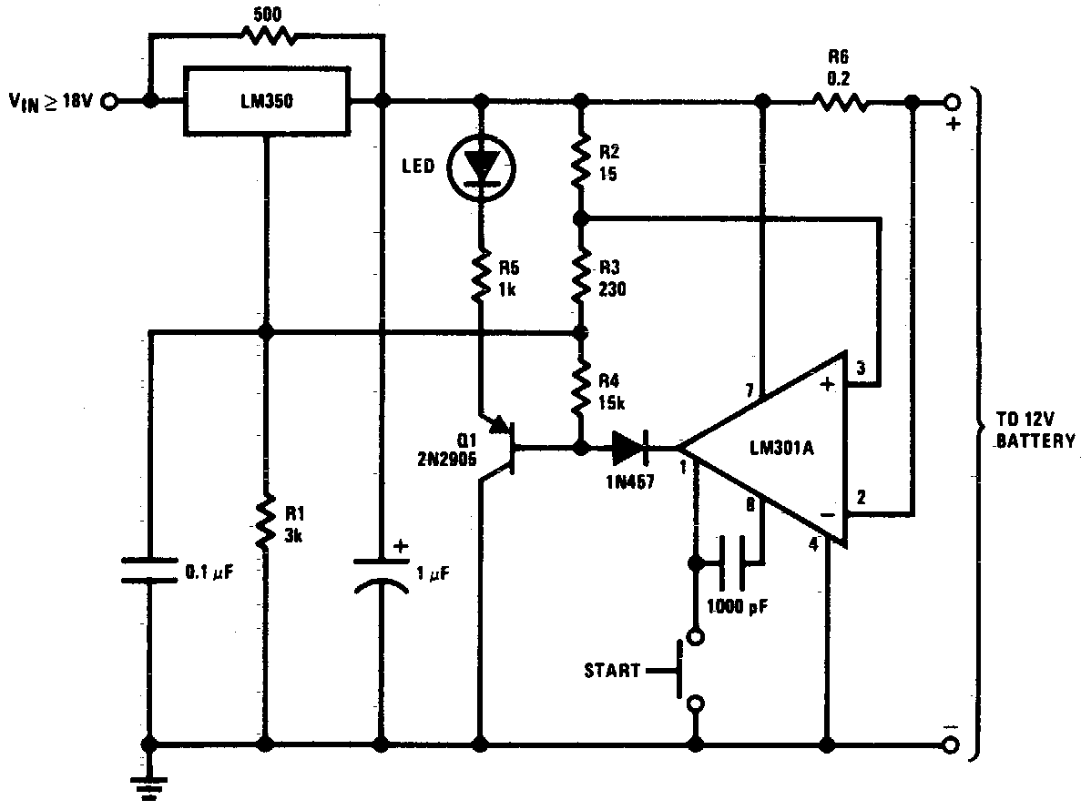
The DC 12V battery charger circuit is designed to efficiently charge gelled electrolyte lead-acid batteries, which are commonly used in various applications due to their reliability and performance characteristics. The circuit typically consists of several key components: a transformer, a rectifier, a filter capacitor, a voltage regulator, and various protection elements such as diodes and fuses.
The transformer steps down the AC mains voltage to a lower AC voltage suitable for charging the battery. The rectifier, often implemented with diodes, converts the AC voltage to pulsating DC. The filter capacitor smooths the output from the rectifier, providing a more stable DC voltage to the battery.
A voltage regulator may be included to ensure that the output voltage remains constant and within safe limits for the battery being charged. This is critical to prevent overcharging, which can damage the battery and reduce its lifespan. Protection components, such as fuses, are incorporated to safeguard the circuit against overcurrent conditions, while diodes can be used to prevent reverse current flow from the battery back into the charger.
The design may also incorporate a charging indicator, such as an LED, to visually indicate the status of the charging process. Overall, this circuit provides a reliable and efficient solution for charging gelled electrolyte lead-acid batteries, ensuring optimal performance and longevity.DC 12V Battery Charger Circuit Diagram. This circuit is a high performance charger for gelled electrolyte lead-acid batteries.. 🔗 External reference
Related Circuits
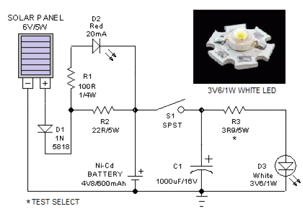
This portable solar lantern circuit utilizes a 6 volt/5 watt solar panel, which is widely available. With this photovoltaic panel, an economical, simple, yet efficient and truly portable solar lantern unit can be constructed. The next essential component required...
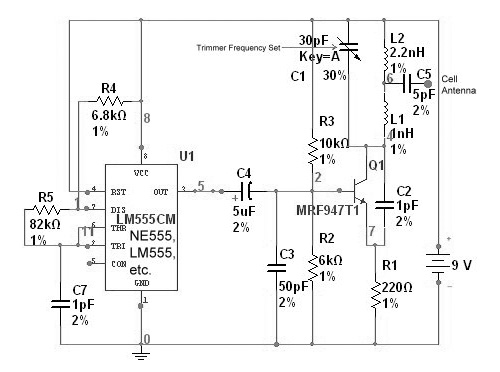
The circuit is based on the NE555 timer, functioning as a simple noise maker, with its output connected to a single transistor oscillator. This oscillator is designed to operate within a frequency range of 800 MHz to 2 GHz,...
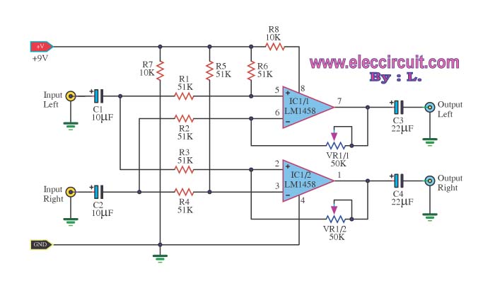
The LM1458 integrated circuit (IC) is utilized to amplify the difference in the left input signal (L), resulting in a surround sound effect. The left signal is coupled through capacitor C2 and resistor R1 to pin 5 of IC1...
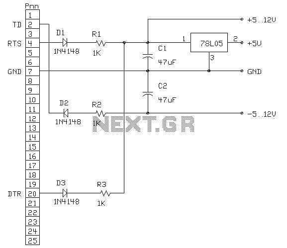
The following circuit is an example of how to get power from an RS-232 serial port. It provides regulated +5V power for logic circuits and also unregulated positive and negative power supplies for the RS-232 transmitting circuit. The circuit...

None of this triggering circuitry is exactly what is desired, but it will provide a starting point in the right direction. The triggering circuitry mentioned serves as a foundational element for various electronic applications, particularly in the realm of signal...
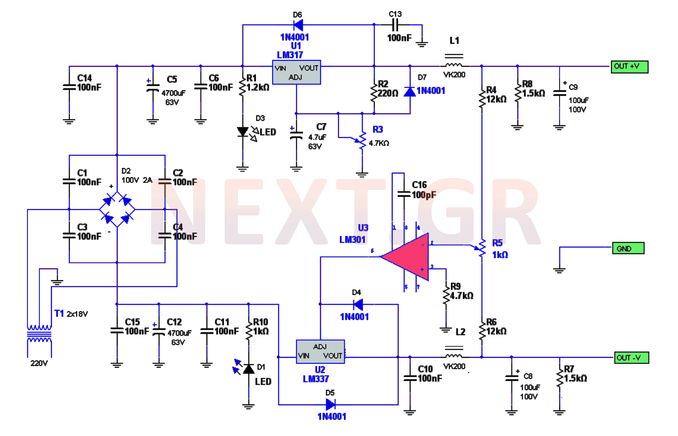
The power supply circuitry includes a 220/2 * 18V / 3.5A transformer, a rectifier, a smoothing filter, a power amplifier (LM301), and two regulators (LM317 and LM337). The voltage from the transformer is rectified by a bridge rectifier. Capacitors...