
resistance soldering circuitry

The triggering circuitry mentioned serves as a foundational element for various electronic applications, particularly in the realm of signal processing and control systems. Such circuits are essential for initiating actions based on specific input signals, which can be derived from sensors, switches, or other electronic components.
A typical triggering circuit may include components such as transistors, operational amplifiers, and resistors to create a reliable response to input signals. For instance, a simple transistor-based trigger circuit can be designed using an NPN transistor that switches on when a certain voltage threshold is reached. This can be achieved by connecting a resistor to the base of the transistor, which controls the current flow and thus the switching behavior of the circuit.
In more advanced applications, integrating operational amplifiers allows for greater sensitivity and control over the triggering conditions. An op-amp can be configured as a comparator, where it compares the input voltage against a reference voltage. When the input exceeds this reference, the output changes state, effectively triggering the desired action.
In conclusion, while the initial triggering circuitry may not meet all specifications, it lays the groundwork for further development and refinement. By selecting appropriate components and configurations, it is possible to enhance the functionality and reliability of the triggering mechanism to suit specific project requirements.None of this triggering circuitry is quite what you want, but it`ll get you started in the right direction .. 🔗 External reference
Related Circuits
This article presents an alternative method for evaluating power supplies that reduces dependency on output voltage and temperature. Traditionally, power supplies have been assessed based on their conversion efficiency, often calculated using commonly used equations. While efficiency serves as...
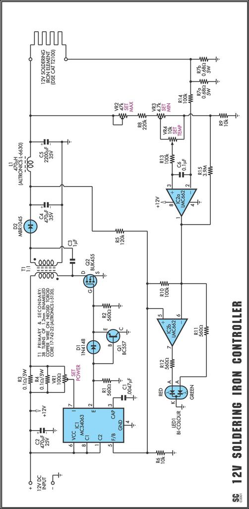
One reason commercial soldering stations are expensive is that they generally require soldering irons with built-in temperature sensors, such as thermocouples. This circuit eliminates the need for a special sensor by sensing the temperature of a soldering iron heating...
The following circuit illustrates the Weller WLC100 Electronic Soldering Station Circuit Diagram. This circuit utilizes the Q4012LPH Transistor. Features include safety measures, temperature control, and functionality as a soldering station that performs effectively for various applications. It is a...
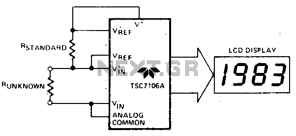
The unknown resistance is connected in series with a known standard resistor, and a current is passed through both components. The voltage developed across the unknown resistor is applied to the input, while the voltage across the known resistor...
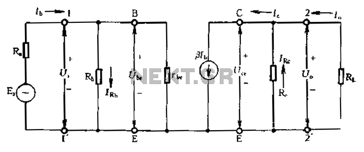
Calculate magnification, input resistance, and output resistance circuit. This circuit is designed to calculate the magnification, input resistance, and output resistance of a given electronic system. The magnification refers to the ratio of the output signal to the input signal,...
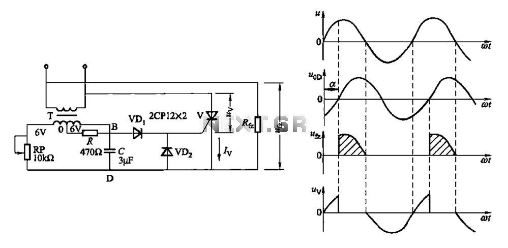
By adjusting the potentiometer RP, the output voltage of the phase shift bridge diagonal changes accordingly, which in turn alters the rectifier load power Rfz. Waveforms at respective points in FIG. 16-1 (b) illustrate this. Resistor R serves as...
Warning: include(partials/cookie-banner.php): Failed to open stream: Permission denied in /var/www/html/nextgr/view-circuit.php on line 713
Warning: include(): Failed opening 'partials/cookie-banner.php' for inclusion (include_path='.:/usr/share/php') in /var/www/html/nextgr/view-circuit.php on line 713