
Monostable circuit
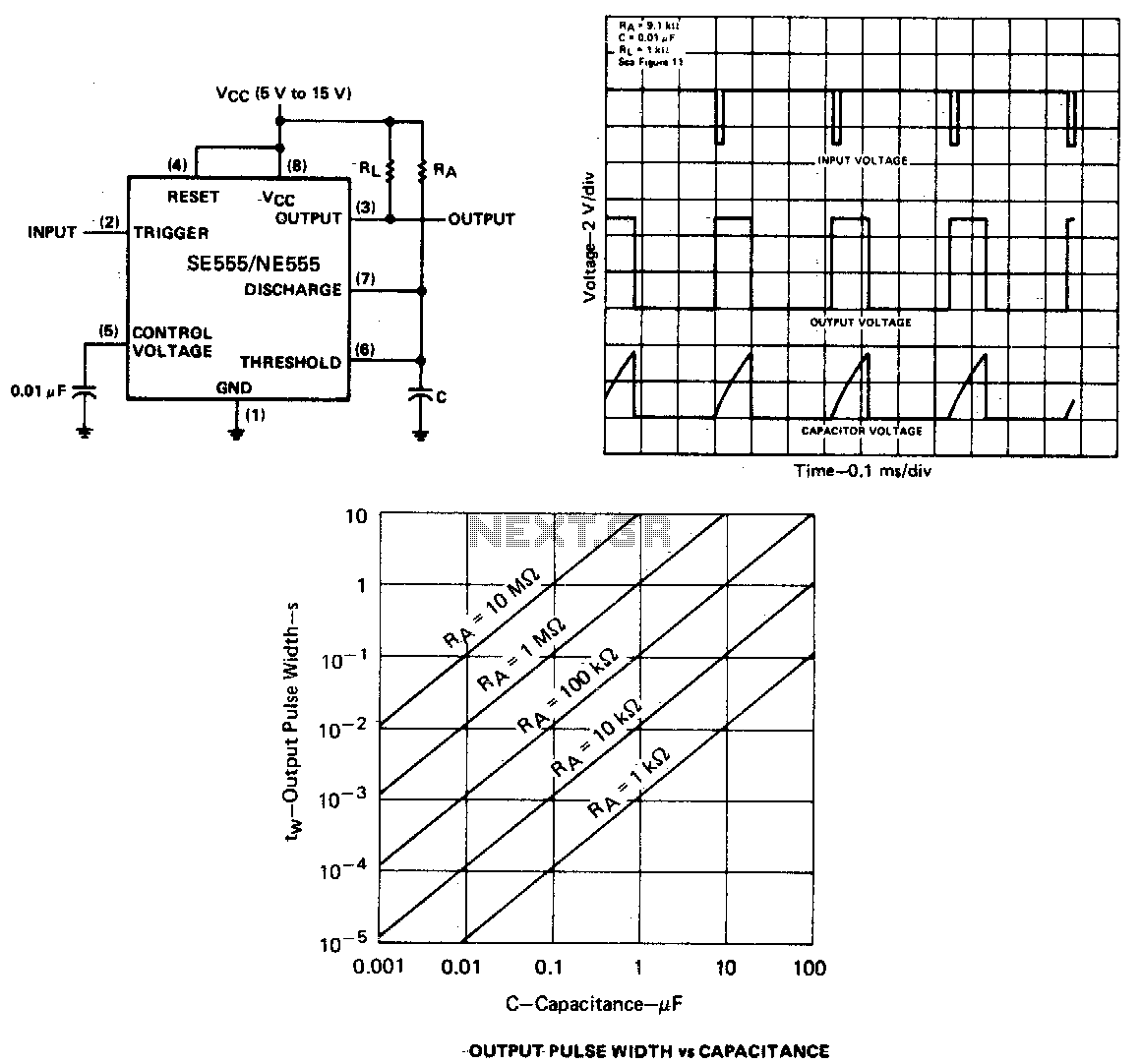
The described circuit primarily utilizes a flip-flop configuration, which is essential for creating a monostable multivibrator. In this setup, the flip-flop serves as the core timing element. The trigger input is crucial for initiating the timing cycle; when a negative pulse is applied, it switches the state of the flip-flop, causing Q to transition low. This transition activates the output, which can drive subsequent components or systems.
Capacitor C, in conjunction with resistor Ra, forms an RC timing network that determines the duration of the output pulse. The charging of capacitor C continues until the voltage across it reaches a predefined threshold. This threshold is critical as it dictates when the threshold comparator will act to reset the flip-flop.
Once the trigger input returns to a high state, the threshold comparator responds by resetting the flip-flop, which in turn causes Q to go high. This transition results in the output being driven low and initiates the discharge of capacitor C through transistor Q1. The timing interval is thus defined by the RC time constant, which is influenced by the values of resistor Ra and capacitor C.
The circuit's behavior ensures that the monostable operation is contingent upon the trigger input remaining high at the conclusion of the timing interval. If the trigger input does not meet this condition, the timing sequence will not complete, demonstrating the circuit's reliance on precise input conditions for proper functionality. This design is commonly used in applications requiring pulse generation, timing, and control sequences in electronic systems.If the output is low, application of a negative-going pulse to the trigger input sets the flip-flop (Q goes low), drives the output high, and turns off 1. Capacitor C is then charged through Ra until the voltage across the capacitor reaches the threshold voltage of the threshold input.
If the trigger input has returned to a high level, the output of the threshold comparator will reset the flip-flop (Q goes high), drive the output low, and discharge C through Ql Monostable operations is initiated when the trigger input voltage falls below the trigger threshold. Once initiated, the sequence will complete only if the trigger input is high at the end of the timing interval. 🔗 External reference
Related Circuits
A high-quality and straightforward intercom circuit utilizing only three transistors. By pressing switch S2, the circuit generates ringing signals. To create a two-way intercom, two identical circuits can be constructed and combined as illustrated in diagram 2. The circuit's...
This presence detector or proximity sensor circuit responds to the presence of any conductive object, including humans. The sensitivity can be adjusted with potentiometer P1, which is positioned at a considerable distance from the rest of the circuit. This...
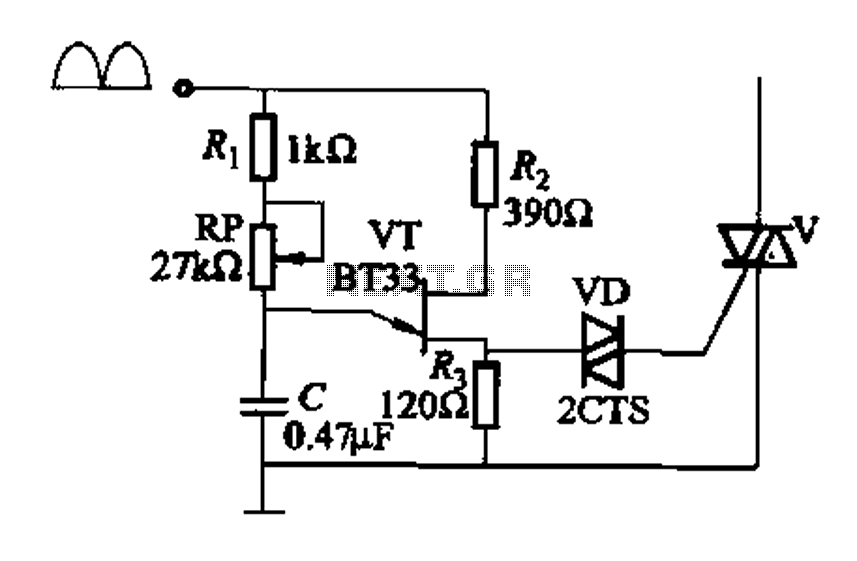
Figure 16-29 (a) illustrates the trigger output through a resistor R2, while Figure 16-29 (b) depicts the integration of a programmable unidirectional transistor (PUT) trigger circuit. The adjustable potentiometer RP can modify the conduction angle of the TRIAC to...
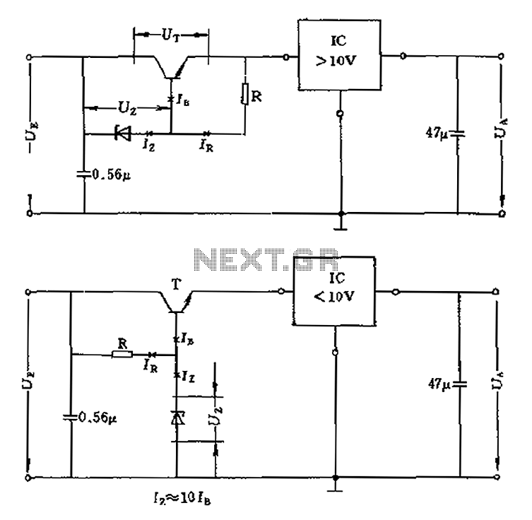
The voltage equation Ue = Ut + Ur + Ua indicates that the transistor voltage Ut will determine the maximum output voltage Ua. Additionally, Ur must be 2V. The voltage regulator's voltage value depends on the selection of Uz....
This is a 25-watt basic power amplifier designed for ease of construction at a reasonable cost. It offers superior performance compared to standard STK module amplifiers commonly found in most mass-market stereo receivers produced today. The 25-watt basic power amplifier...
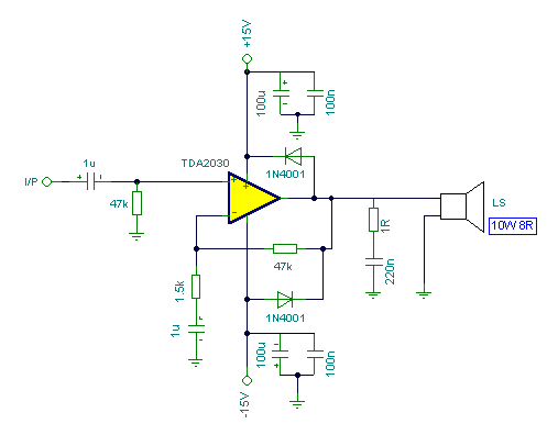
Connecting two TDA2030 through inexpensive power transistors allows for the creation of an amplifier capable of delivering higher power. This can be achieved by utilizing the component values specified in the schematic. To implement this circuit, two TDA2030 integrated circuits...