
DC Circuits
The behavior of electrons in a conductor under the influence of an electric field is a fundamental concept in electronics. The random motion of electrons in the absence of an electric field illustrates the intrinsic nature of charge carriers in conductive materials. The introduction of an electric field results in a net drift velocity, which is critical for the conduction of electricity. The analogy of a ball rolling down an inclined plane effectively captures the essence of this drift, emphasizing how external forces influence the motion of charged particles.
The concept of electrical resistance is pivotal in understanding how materials respond to electric currents. The arrangement of atoms within a conductor determines how easily electrons can move through it. As temperature increases, the increased kinetic energy of the atoms leads to more frequent collisions with electrons, thereby increasing resistance. This relationship is quantitatively described by the temperature coefficient of resistivity, which allows for predictions about how a material will behave under varying thermal conditions.
The mathematical formulation of resistance, R = ρL/A, encapsulates the relationship between resistance, resistivity, length, and cross-sectional area, providing a clear framework for analyzing different conductive materials. The resistivity, a material-specific property, varies with temperature, necessitating careful consideration in circuit design and material selection.
Ohm's Law further elucidates the relationship between voltage, current, and resistance, forming the foundation for circuit analysis. The linear relationship depicted in V vs. I graphs serves as a practical tool for engineers to evaluate the performance of electrical components. Understanding these principles is essential for designing efficient circuits and systems, ensuring optimal performance in various applications.Electron trajectories in a conductor are shown in the diagrams below. If there is no electric field inside a conducting material electrons move randomly. If a field is present the electric force F=qE imposes a small drift on the electron`s motion. Note that since the electron has a negative charge the force F is in a direction opposite to the field E. rolling down an inclined plane and bouncing off pegs in its path is analogous to the motion of an electron in a metallic conductor with an electric field present. Electric charges move through a material in a similar way. If the charge has its motion greatly restricted we say the material through which it is moving has a large electrical RESISTANCE.
The resistance of a material depends on the arrangement, or spacing, of the atoms or molecules in the material. The motion of the atoms affects the electrical resistance of the material. If the atoms or molecules vibrate a lot, in general, they will increase the resistance of the material.
And since we know that as the temperature rises molecules vibrate more and more, we conclude that the electrical resistance of a material is increased as the temperature rises. The amount of electrical resistance caused by a temperature increase is described by factor (a) called the temperature coefficient of resistivity (resistivity is closely related to resistance).
Other factors that affect the resistance of an electrical conductor are its length and cross-sectional area. The longer the conductor the greater the resistance, and the greater the cross-section area through which the charges flow the smaller the resistance of the conductor.
We can formulate these ideas in an equation relating the resistance, the resistivity, the length, and the area of a conductor. Since the resistance is proportional to the length and inversely proportional to the area we can say that R = r L / A, where we have inserted a constant of proportionality called the resistivity (r).
The resistivity is dependent on the characteristics of the material and its temperature and is, in general, different for each material (in units of ohm-meters). The dependence of resistance (R) or resistivity (r) on temperature has been found to be linear over limited temperature ranges and can be described as a straight line: where T is the Celsius temperature, To is the reference temperature (usually room temperature or 20 degrees C), Ro is the resistance at the reference temperature, and a is the temperature coefficient of resistivity in units of 1/degrees C.
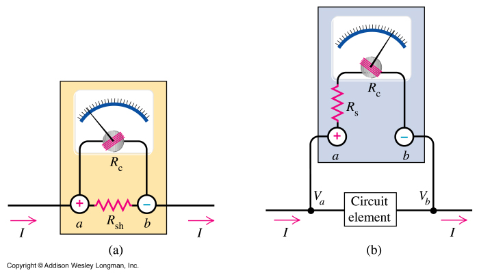
You will measure the variation of resistance with temperature in the lab and verify the accuracy of this equation. Current through a conductor flows from a higher electric potential (or voltage) to a lower electric potential; just as water flows from a higher level of potential energy to a lower level of potential energy, i.
e. , downhill! The greater the electric potential between the ends of a conductor, the greater the current through the conductor. The difference in voltage levels is often referred to as the voltage. If the current in a conductor is proportional the the potential difference (or voltage) driving the current through the conductor we say that Ohm`s Law is obeyed: V = I R, where R, the resistance of the conductor, is the constant of proportionality or the slope of the V vs.
I graph. See the V vs. I graphs below. Not all o 🔗 External reference
Related Circuits
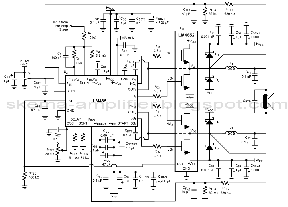
This project is an audio amplifier designed to amplify output signals from small radios, tape players, CD players, or other audio signal sources. For stereo operation, two identical amplifiers must be constructed—one for the left channel and another for...
The LA4440 is a two-channel audio power amplifier integrated circuit (IC) designed for stereo and bridge amplifier applications. In dual mode, it provides an output of 6 watts per channel, while in bridge mode, it can deliver up to...
The curves for a capacitor exhibit significant non-linearity, which can be utilized in circuits to modulate, demodulate, and multiply frequencies. This characteristic is known as non-linear reactance rather than resistance, resulting in minimal energy loss. The charge stored in...
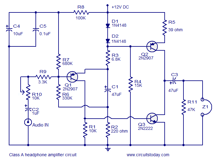
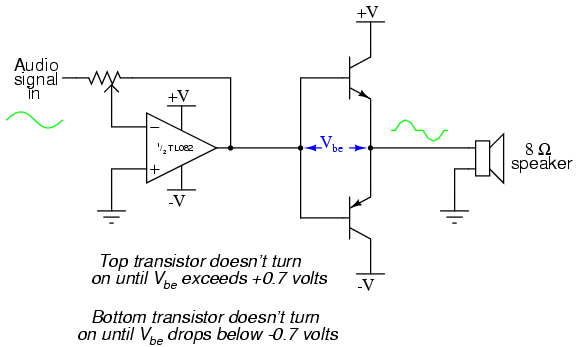
Transistor amplifier circuits that are simple and easy to construct. This includes a headphone amplifier, a four-transistor amplifier, and a low-power amplifier. Transistor amplifier circuits are fundamental components in electronic design, offering various applications ranging from audio amplification to signal...
A straightforward method to create a speaker transformer involves winding turns around a ferrite rod. The primary winding consists of 300 turns of 0.01mm wire, which is very fine, wound over the secondary and concluding with a loop of...
An astable multivibrator is an electronic device that continuously alternates between two states in its output. When one state is high, the other is low. This characteristic is useful for generating a continuous stream of pulses without the need...
Warning: include(partials/cookie-banner.php): Failed to open stream: Permission denied in /var/www/html/nextgr/view-circuit.php on line 713
Warning: include(): Failed opening 'partials/cookie-banner.php' for inclusion (include_path='.:/usr/share/php') in /var/www/html/nextgr/view-circuit.php on line 713