
varactor diodes circuits
The described circuit utilizes the non-linear properties of capacitors and diodes to achieve frequency multiplication through harmonic generation. The fundamental principle relies on the behavior of the varactor diode, which changes its capacitance based on the applied voltage, facilitating the generation of harmonics when exposed to RF signals. The design of the circuit is critical, as the tuning of the coils (L1 and L2) must be precise to ensure optimal resonance at the desired frequencies. The use of high-quality components and careful tuning techniques will enhance the performance of the circuit, allowing for efficient frequency multiplication while minimizing losses. The interaction between the fundamental frequency and its harmonics creates a rich output spectrum, which can be exploited in various applications, including signal processing and communication systems. The ability to demodulate AM signals and remodulate them at a different frequency is particularly valuable in modern RF applications, indicating the versatility and effectiveness of non-linear reactive components in electronic design.The curves for a capacitor are all markedly non-linear and this property can be used as an element in a circuit to modulate, demodulate and multiply frequency. This is non-linear reactance, rather than a resistance, however, and because of this, very little loss occurs.
The charge in a capacitor is equal to the capacitance multiplied by the voltag e across the capacitor: Q = CV, and the capacitance/voltage curves above approximate very roughly to the reciprocal of the square root of the applied voltage. Combining Q = CV and C approx l/V*0. 5, the charge on the capacitor can be seen to be proportional to the square root of the voltage. If an RF voltage is applied to a capacitative reactance which behaves in this manner, a heavily distorted charge, consisting mainly of the second harmonic of the input, is produced and can be tapped off using a tuned circuit.
A diode used this way is called a varactor diode. This action can easily be demonstrated by using a zener diode as the non-linear element and a signal generator tuned to about 500kHz giving an output of about 0. 25 to 0. 5V rms. In diagrams (a) and (b) above the circuit is in two halves: the left-hand part is tuned to 500kHz and the right-hand part to 1MHz.
RF current is passed through the diode at 500kHz and, due to the non-linear reactance of the diode, a proportion of its second harmonic will (or should be) circulating in the right-hand part of the circuit. L1 and L2 are IF transformer coils: L1 could be two coils in series (aiding), tuned to resonate at 500kHz with the diode in circuit, and L2 one coil tuned to resonate at 1MHz.
Resonance can be measured across the complete coil with a low-capacitance, high-impedance RF probe. Having tuned each circuit, apply 500kHz to L1 and measure the output across L2. Tune this coil up very carefully (the resonance peak is very sharp). To prove this frequency has been produced by the diode and is not just generator harmonics slipping through, apply 1MHz from the generator to L1 and see how much of this gets through to the output. With any reasonable Q in the coils, it will not be very much. Another proof would be to replace the diode with an equivalent capacitance; the output will go down to a very low proportion of the previous value.
Other harmonics can be produced in a similar way. The second harmonic can mix with the fundamental and produce the third, and the second can produce its own distorted charge for the fourth harmonic, although the output of the fourth harmonic is improved if the third is produced as well. In all these circuits for multipliers, current must be allowed to circulate through the diode at all the respective frequencies by circuits that are tuned to those frequencies.
These circuits, excepting the output circuit, are called idlers. All tuned circuits have to be of the maximum unloaded Q to minimize circuit loss and they can be considered either as parallel- or series-tuned, depending on which way one looks at them Various varactor multipliers: doubling in (a), tripling in (b) and quadrupling or quintupling in (c). (d) shows a way of altering the bias to make the input RF lie along some other point of the curve and possibly to improve the effect.
the diode average capacitance (at a certain voltage) is in series with the tuning capacitance and both of these tune the coil. A properly-designed doubler of this kind, using a diode specifically meant for this function, can give an output of about 90 per cent of the input, the rest being dissipated in circuit resistances.
When multipliers of this sort were first used, some surprise was expressed that they could be fed with an AM input. This cannot normally be done with a frequency multiplier, at least to get a coherent output, but it seems that a non-linear reactance can demodulate at the input frequency and remodulate at the output frequency (with a little added harmonic distortion), to give an output whi
🔗 External reference
Related Circuits
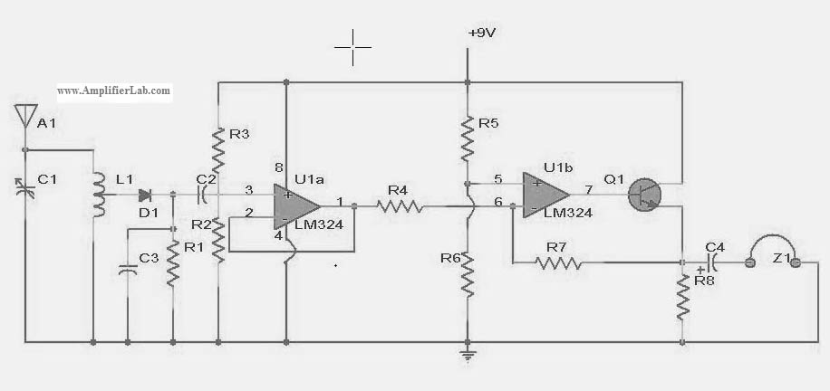
The following circuit illustrates a power amplifier electronic circuit, specifically a tube audio RF amplifier circuit diagram. This circuit is based on the LM324 integrated circuit. The power amplifier circuit utilizing the LM324 operational amplifier is designed to enhance audio...
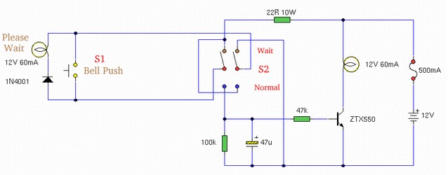
This article outlines various audiophile projects, including the DDDAC 2000, and discusses components such as the 1N4001 diode. The content is straightforward and informative, providing insights into these projects. For instance, readers can find and purchase the 1N4001 diode...
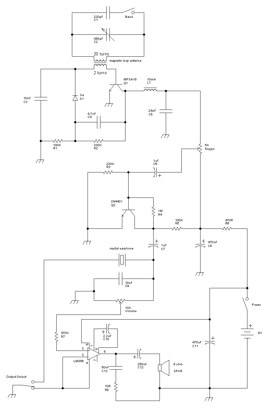
This receiver is a modification of Charles Wenzel's Two Transistor Reflex Radio. Instead of a ferrite AM loopstick antenna, a magnetic loop antenna is used, and an LM386 amplifier stage has been added to drive an 8-ohm speaker. A...
This circuit is designed to drive a relay coil using a low power output, typically from an integrated circuit (IC) such as a 555 timer or a TTL/CMOS device. It facilitates the switching of high loads or loads requiring...
High Power Siren Circuit. This article discusses a robust siren circuit suitable for various applications. A complementary transistor pair (BC557 & BC337) is configured as an oscillator to directly drive the speaker. Transistor Q1 (BC557) is utilized to ensure...
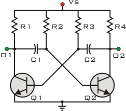
What exactly is a multivibrator? I suppose one definition would be 'a circuit which has several states'. This will do for now, it's quite loose so leaves plenty to the imagination! Conventional multivibrators have only two stages and come...