
100Watt Inverter 24VDC to 220VAC II
The 100-watt inverter circuit utilizes the CD4047 integrated circuit, which is a versatile astable multivibrator that can generate square wave signals. This IC is responsible for creating the necessary pulse-width modulation (PWM) signals that drive the MOSFET IRF540. The IRF540 is a powerful N-channel MOSFET that allows for efficient switching and control of high voltages and currents, making it suitable for inverter applications.
The circuit typically includes a transformer with a primary winding rated for 220VAC and a secondary winding that is capable of handling the output current required by the load. The transformer is crucial for stepping up the voltage to the required level while isolating the inverter from the load. The choice of a 2-3A transformer indicates that the inverter can deliver a continuous output of up to 100 watts, which is suitable for powering various household appliances.
Additional components in the circuit may include capacitors for filtering and stabilization, resistors for biasing and feedback, and diodes for protection against back EMF generated by the inductive load. Proper layout and thermal management are essential in this design to ensure the MOSFET operates within safe limits, preventing overheating and potential failure.
In summary, this inverter circuit design is an efficient solution for converting low-voltage DC to high-voltage AC, utilizing the CD4047 and IRF540 to achieve reliable performance for 220VAC applications.This is another 100watt inverter circuit diagram. Built based on IC CD4047 and Mosfet IRF540, this inverter have ability to supply electronic device -which require 220VAC- up to 100w from 2-3A transformer.. 🔗 External reference
Related Circuits
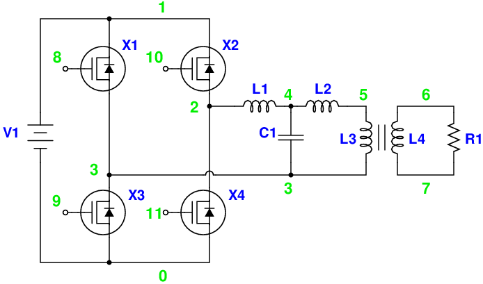
Magic Sinewave Analysis using SPICE and a Simple Inverter Circuit. This document discusses the analysis of a sinewave signal generated by a simple inverter circuit using SPICE simulation software. The inverter circuit is designed to convert a DC input voltage...
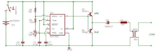
This circuit is a DC to AC inverter utilizing a 555 timer and a transformer with a specification of 9-0-9V/230V and a rating of 36VA. Key components include a 555 integrated circuit (IC), TIP42C, and TIP41C transistors. The described circuit...
This document describes a 100 Watt inverter circuit that utilizes a minimal number of components. The circuit employs the CD 4047 integrated circuit (IC) from Texas Instruments to generate 100 Hz pulses, along with four 2N3055 transistors that drive...
This is a high-power inverter circuit designed to deliver an AC power output of 3000W. It converts 12 Volt DC battery voltage into a square wave voltage with a frequency of 50 Hz and a duty cycle of 25%. The...
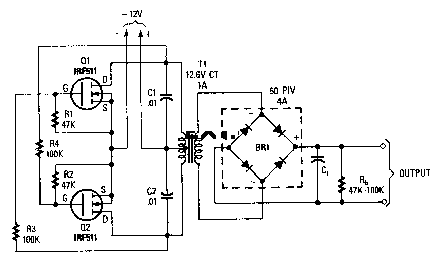
This inverter can deliver high-voltage AC or DC, with a rectifier and filter, up to several hundred volts. The secondary and primary of T1, a 12.6 to 440 V power transformer, respectively, are reversed; e.g., the primary becomes the...
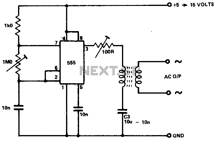
The circuit is designed to supply power for portable Geiger counters, dosimeter chargers, high resistance meters, and similar devices. The 555 timer integrated circuit (IC) operates in its multivibrator mode, with the frequency adjusted to optimize the characteristics of...