
Equipment controller with PC
Lots of ways to control the hardware can be implemented using software. In C/C++ one can use the outportb(portno,value) function where portno is the parallel port address (usually 378hex for LPT1) and 'value' is the data that is to be sent to the port. For a value=0 all the outputs (D0-D7) are off. For value=1 D0 is ON, value=2 D1 is ON, value=4, D2 is ON and so on. eg. If value=29(decimal) = 00011101(binary) ->D0,D2,D3,D4 are ON and the rest are OFF.
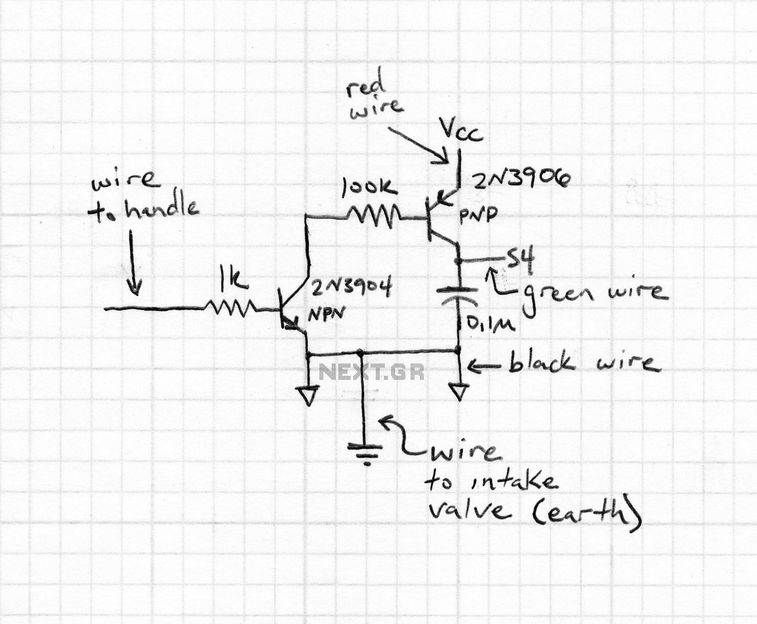
The circuit utilizes a standard 25-pin parallel printer port, commonly found on older PCs, for the control of multiple devices. The primary function of the circuit is to enable control of up to eight devices (or equipment) through the use of digital output lines D0 to D7. Each output line corresponds to a specific pin on the parallel port, where pin 2 is assigned to D0, pin 3 to D1, and so forth up to pin 9 for D7.
The interface circuit is designed with an opto-coupler, which serves as an interface between the computer's parallel port and the relay driver circuitry. This configuration is crucial as it provides electrical isolation, protecting the PC from any high voltages or currents that may be present in the controlled devices. The opto-coupler operates by allowing the control signal from the parallel port to activate an internal LED, which in turn triggers a phototransistor to close the relay circuit.
In terms of software control, the implementation can be done using C or C++ programming languages. The `outportb` function is utilized to send data to the parallel port, where the first parameter is the port address, typically 378h for LPT1, and the second parameter is the value representing the state of the outputs. The binary representation of the value determines which outputs are activated; for instance, a value of 29 in decimal translates to the binary 00011101, which means that D0, D2, D3, and D4 are turned ON while D1, D5, D6, and D7 remain OFF.
This setup allows for flexible control of various devices, such as motors, lights, or other electronic components, by simply adjusting the output values sent to the parallel port. The circuit can be expanded by replicating the interface circuit for each additional device, ensuring that all eight outputs can be independently controlled. Here is a circuit for using the printer port of a PC, for control application using software and some interface hardware. The interface circuit along with the given software can be used with the printer port of any PC for controlling up to eight equipment .
The interface circuit shown in the figure is drawn for only one device, being controlled by D0 bit at pin 2 of the 25-pin parallel port. Identical circuits for the remaining data bits D1 through D7 (available at pins 3 through 9) have to be similarly wired.
The use of opto-coupler ensures complete isolation of the PC from the relay driver circuitry. Lots of ways to control the hardware can be implemented using software. In C/C++ one can use the outportb(portno,value) function where portno is the parallel port address (usually 378hex for LPT1) and 'value' is the data that is to be sent to the port. For a value=0 all the outputs (D0-D7) are off. For value=1 D0 is ON, value=2 D1 is ON, value=4, D2 is ON and so on. eg. If value=29(decimal) = 00011101(binary) ->D0,D2,D3,D4 are ON and the rest are OFF. 🔗 External reference
Related Circuits
The first phase of a motion-controlled photography rig has been completed, focusing on the setup of bipolar stepper motor controllers. This component is crucial for motor control, which is essential for achieving motion in the project. A list of...
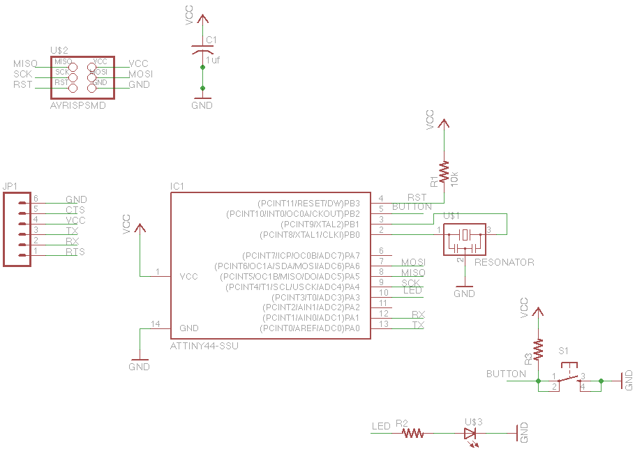
For this week's assignment, a chip design was provided, and the task was to incorporate a button and an LED (light-emitting diode). The objective was to fabricate the chip and program it to interact with the light and button....
An alphanumeric low-cost LCD display is essential for many small and large projects to display various types of information. The Hitachi HD44780 chipset-based 16x2 character LCD is very affordable and easily available in the local market. This project covers...
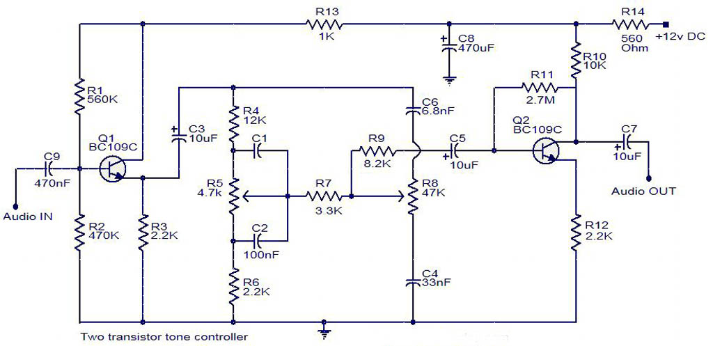
The electrical schematic diagram presented below illustrates a simple two-transistor tone controller audio circuit, which is available for free download. This circuit is based on the well-known Baxandall tone control design. Variations in the values of the transistor components...
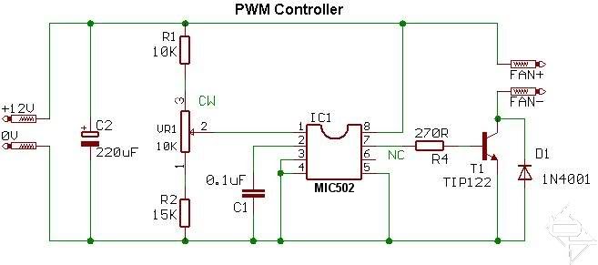
This circuit diagram illustrates the design for each individual channel. A modification was made by replacing the 0.1 µF timing capacitor with a 100 pF capacitor to enhance performance. The original 0.1 µF capacitor caused the fans to produce...
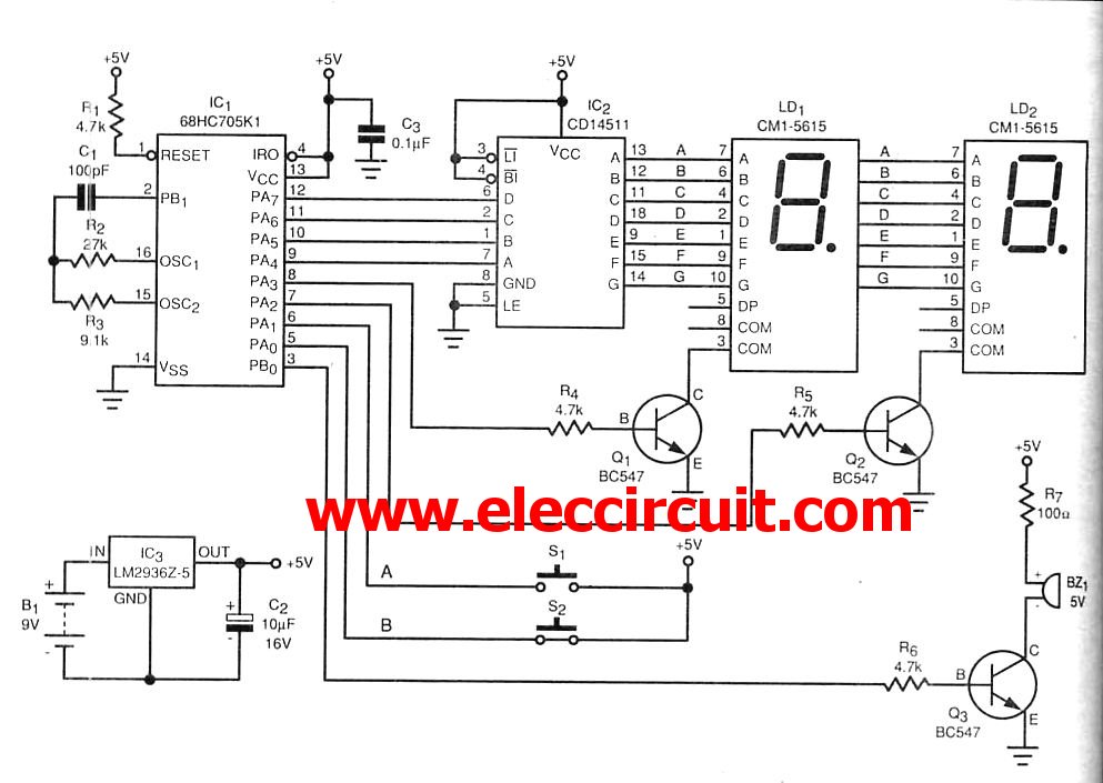
The microcontroller IC is a device that resembles a typical integrated circuit. However, it contains a miniature computer within its architecture. This device can serve as a replacement for transistors. Microcontroller integrated circuits (ICs) are compact, multifunctional devices that integrate...