
DC Fan Control (Switching on/off)
The MC25060V2 fan is a DC brushless fan typically used for cooling applications. To control this fan electronically, a low-side switch configuration is suitable. The low-side switching method involves connecting the switching device (either an NPN BJT or an N-channel MOSFET) between the ground and the fan. When the microcontroller GPIO pin outputs a high signal (5V), the switching device turns on, allowing current to flow through the fan, thus activating it. Conversely, when the GPIO pin is low, the fan is turned off.
When choosing between an NPN BJT and an N-channel MOSFET, several factors should be considered. N-channel MOSFETs generally have lower on-resistance compared to BJTs, resulting in less power dissipation and heat generation, which is beneficial for efficiency. Additionally, MOSFETs are voltage-driven devices, meaning they require less input current to switch on, making them suitable for microcontroller applications where GPIO current sourcing capability may be limited.
In contrast, BJTs are current-driven devices and may require a base resistor to limit the current flowing from the GPIO pin. This can complicate the design and may not be as efficient as using a MOSFET. Furthermore, BJTs typically have a slower switching speed compared to MOSFETs, which might be a consideration depending on the intended application.
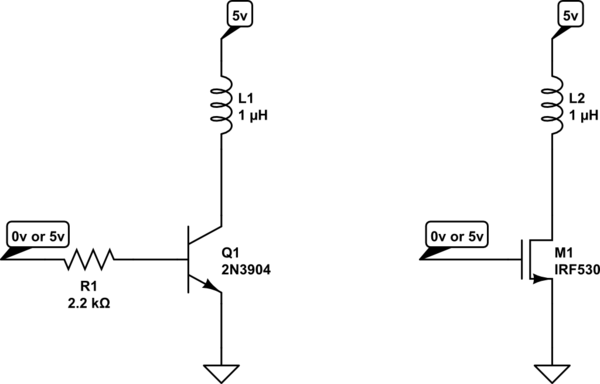
For the schematic representation, the fan can be modeled as an inductive load. The low-side switch (BJT or MOSFET) is connected to the negative side of the fan, while the positive side connects to the power supply. A flyback diode should be included across the fan to protect the switching device from voltage spikes generated when the inductive load is turned off. This diode should be oriented to allow current to flow when the fan is switched off, preventing damage to the switching device.
In summary, the choice between an NPN BJT and an N-channel MOSFET for controlling the MC25060V2 fan through a microcontroller GPIO pin should consider factors such as efficiency, switching speed, and complexity of the control circuit. The schematic design should include necessary protective components to ensure reliable operation.Using an MC25060V2 fan, and I`d like to switch it on and off through software occasionally (i. e. not PWM or anything fancy like that). My thought is to either put an NPN BJT or a N-channel MOSFET on the low side and control it`s gate with a 5V microcontroller GPIO pin. Any reason I should choose one technology over the other (or another approa ch altogether) Here are schematic representations of what I`m proposing (just logical, representing fan as an inductor and part numbers / values not important). 🔗 External reference
Related Circuits
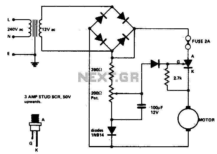
Low voltage speed control provides excellent starting torque and effective speed regulation. Additionally, a reversing switch can be integrated into the motor leads. Low voltage speed control circuits are essential in applications where precise motor control is required, such as...
This simple DC motor control or PWM circuit using a 555 IC can be utilized to regulate the speed of a DC motor. The circuit is straightforward and can be assembled quickly if all components are readily available. The described...
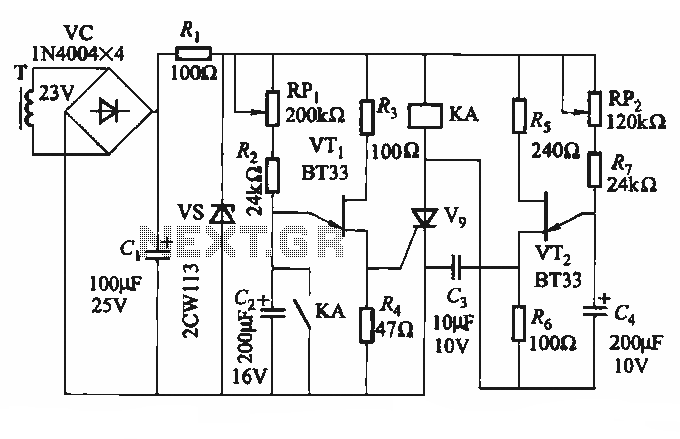
The circuit depicted in Figure 3-69 is designed for applications requiring frequent timing control for motor reversing operations. In this configuration, thyristors V1, V2, and V7 are utilized for positive control of motor rotation, while thyristors V3, V4, V5,...
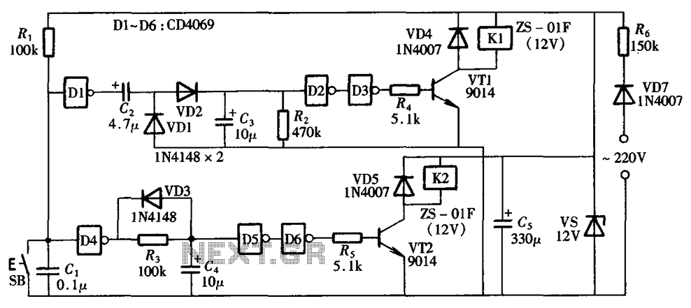
A one-button control switch is designed to control two relays, each of which can switch the load power on and off as needed. The circuit primarily consists of a hex inverter CD4049 and two self-locking DC relays. The circuit utilizes...
This unit provides 2-way IR communications using a numeric keypad and an LCD display. Data is sent and received in ASCII with no regard to what the data means to any particular device. The ASCII data still needs some...
This is a Voltage Controlled Oscillator (VCO) circuit. This circuit is based on a Hartley oscillator. The frequency depends on the values of C1 and L1. The Voltage Controlled Oscillator (VCO) circuit described operates using a Hartley oscillator configuration, which...