
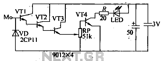
Timing SCR control motor reversing circuit
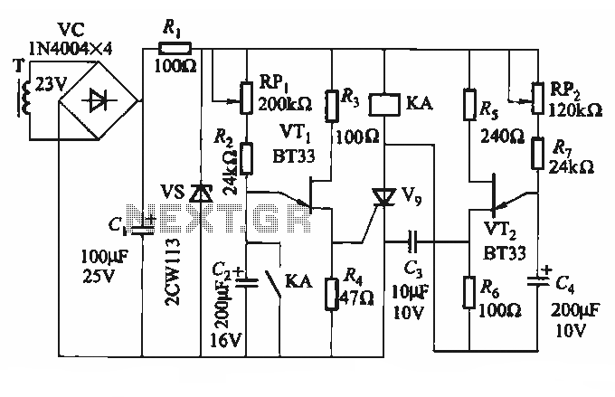
The circuit operates by utilizing thyristors, which are semiconductor devices that can control power. Thyristors V1, V2, and V7 are connected in a manner that allows for the positive rotation of the motor, enabling it to run in a forward direction. Conversely, thyristors V3, V4, V5, and V6 are configured to facilitate the motor's reverse operation. The switching between forward and reverse is achieved through the control of the single-junction transistor VT1, which acts as a trigger for the thyristors, and the delay circuit incorporating VT2, which regulates the timing of the switching action.
The protection of the thyristors is critical to ensure reliable operation and longevity of the circuit. Resistor R and capacitor C are strategically placed to absorb voltage spikes that may occur during the switching process, thereby preventing damage to the thyristors. This protective measure enhances the robustness of the circuit, allowing it to withstand the stresses associated with frequent motor reversing.
Furthermore, the inclusion of adjustable potentiometers RPi and RP2 provides flexibility in the operation of the motor. By varying the resistance values of these potentiometers, the user can fine-tune the duration of the forward and reverse running times, accommodating different operational requirements. This adjustability is particularly advantageous in applications where precise timing control is essential, such as in automated systems or robotics.
Overall, this circuit exemplifies an effective solution for controlling motor direction and timing, integrating advanced semiconductor technology with practical design considerations for enhanced performance and reliability.Circuit shown in Figure 3-69. It applies to require frequent timing control motor reversing operation of the occasion. Drawing, thyristor Vl, V2 and V7, vs used as a positive control rotation, V3, V4 and V5, V6 used inversion control; motor forward running and reverse running time, respectively, by the extension of single-junction transistor VTi and the like of the circuit configuration and the like by the VTz delay circuit to control; the resistor R and the capacitor C is used for the thyristor protection. Adjust potentiometer RPi and RPz, can change the motor running forward and reverse running time respectively.
Related Circuits
The welder no-load power saver circuit consists of a current detection control circuit and a power saving control circuit, as illustrated in the accompanying chart. The current detection control circuit includes a current transformer (TA), a bridge rectifier (UR),...
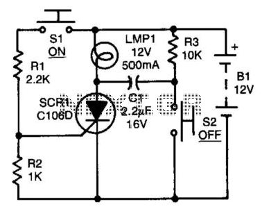
After the SCR is activated, capacitor CI charges up to nearly the full supply voltage through resistor R3 and the anode of the SCR. When switch S2 is later closed, it grounds the positive terminal of CI, causing the...
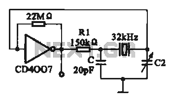
A 32 kHz clock oscillator is essential for digital circuits, as depicted in the schematic. The 32 kHz crystal clock oscillator serves to provide a time reference signal for the digital circuit. It utilizes a CMOS integrated circuit, specifically...
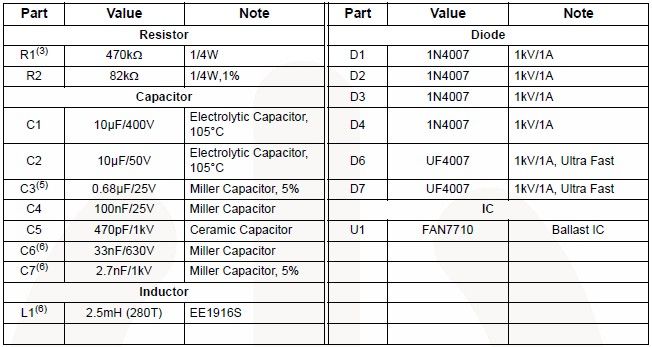
The FAN7710 Ballast Control IC for Compact Fluorescent Lamps, developed using Fairchild's unique high-voltage process and system-in-package (SiP) concept, enables the design of a simple and low-cost fluorescent lamp driver electronic project. The FAN7710 ballast control manages internal high-voltage...
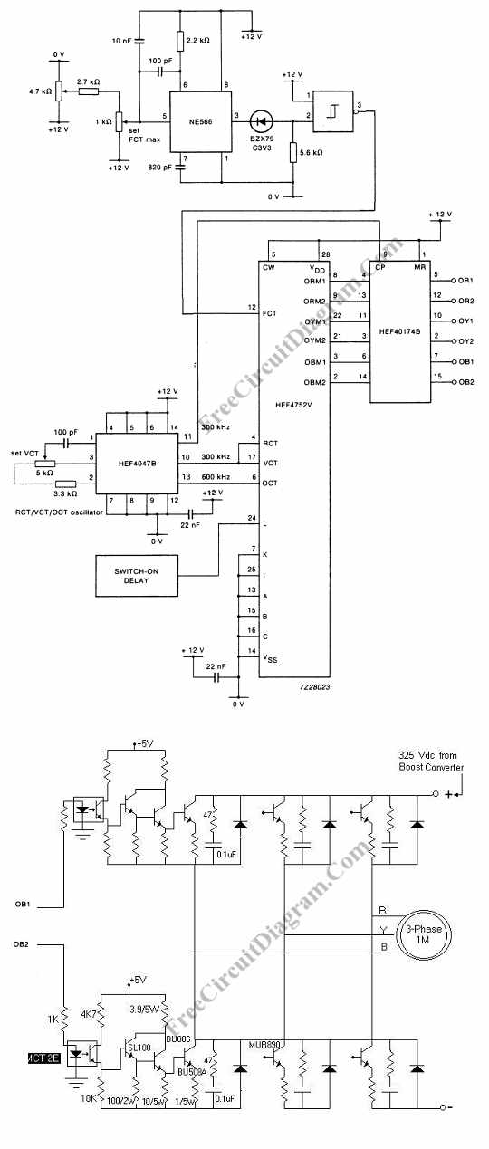
Controlling the speed of a three-phase AC motor is achieved by regulating the frequency of the power supply, as the motor operates in synchronization with the line. To control the speed of a three-phase AC motor, it is essential to...
The internal disconnection circuit for a blanket operates on the principle of induction. It includes a wire approximately 2 cm in length that senses the proximity of a charged mains power source. When the sensing wire is close to...