
Voltage Controlled Oscillator with Varactor
The Voltage Controlled Oscillator (VCO) circuit described operates using a Hartley oscillator configuration, which is a type of LC oscillator known for its simplicity and effectiveness in generating oscillations. In this circuit, the frequency of oscillation is primarily determined by the inductance (L1) and capacitance (C1) components used in the design.
The Hartley oscillator consists of two inductors and one capacitor. In this configuration, the inductors are typically connected in series or parallel to form a feedback loop that sustains oscillation. The frequency of the output signal can be expressed using the formula:
\[ f = \frac{1}{2\pi\sqrt{L_{total} \cdot C}} \]
where \( L_{total} \) is the effective inductance of the inductor network and \( C \) is the capacitance. In a VCO, the capacitance (C1) can be varied by using a variable capacitor or a combination of fixed and variable capacitors to achieve a range of frequencies. This allows for dynamic control of the output frequency based on the input voltage.
The circuit typically includes a transistor or operational amplifier that amplifies the oscillation signal, along with additional components for biasing and stability. The output of the VCO can be used in various applications, including frequency modulation, phase-locked loops, and signal generation for communication systems.
In practice, careful selection of the values for L1 and C1 is critical to achieving the desired frequency range and stability of the oscillator. Additionally, the circuit may incorporate filtering and buffering stages to ensure that the output signal maintains integrity and is suitable for further processing or transmission.This is a Voltage Controlled Oscillator? (VCO) circuit. This circuit is based on Hartley oscillator. The frequency depend on the value of C1 and L1. The. 🔗 External reference
Related Circuits
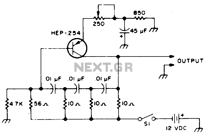
The following transistors may be used: HEP-254, OC-2, SK-3004, AT30H. To increase the frequency, decrease the value of the capacitors in the ladder network. The transistors listed, HEP-254, OC-2, SK-3004, and AT30H, can serve various roles in electronic circuits, particularly...
Most operational amplifier circuits require a dual-polarity power supply - one having +V and -V. However, there are times when a DP supply simply isn't conveniently available. Single-polarity modifications to DP designs often achieve their effect by referencing the...
All miniature electronic devices operate off batteries. Some of them require higher than the standard battery voltages for efficient operation. If a battery with the specific voltage is unavailable, additional cells must be connected in series to increase the...
The design is based on the TubeHobby and serves as the power supply used in their NC2. This kit was constructed as an initial project involving nixie tubes, and a review of this excellent kit can be found in...
The circuit depicted is designed to protect a system from power supplies that may exceed safe limits. An example of this is small consumer products that utilize external AC adapters, where there is a risk of accidentally connecting the...
To obtain the power supply graphs on the previous page, the circuit is designed to independently monitor the power sources with the addition of a few resistors. Diode D3 allows the solar panel voltage to charge the batteries, while...