
Dc lamp dimmer

U1 drives the gate of transistor Q1, enabling it to switch the lamp ON and OFF at a frequency that is proportional to the duty cycle of the multivibrator.
This circuit operates on a simple principle of pulse-width modulation (PWM), allowing for efficient control of the lamp's brightness without significant power loss. The multivibrator generates a square wave signal, which modulates the power delivered to the lamp. The duty cycle of this signal, adjustable via the potentiometer R3, determines the average power reaching the lamp, thus controlling its brightness.
The components involved play specific roles: the capacitors (C1 and C2) store energy and help determine the timing characteristics of the multivibrator, while the resistors (R1, R2, R3, and R4) set the frequency and duty cycle of the PWM signal. The transistor Q1 acts as a switch, responding to the output from the multivibrator to control the lamp's operation.
This design is particularly advantageous for portable applications, such as flashlights, where battery life and heat management are critical. The low power consumption and minimal heat generation make this circuit suitable for long-duration use, ensuring that the flashlight can operate efficiently without overheating or requiring complex thermal management solutions.A low power, low cost dc lamp dimmer for a two-wire portable "flashlight" can be realized with little or no heatsinking. In addition, a single potentiometer, R3 adjusts lamp brightness. Battery power is stored in Cl for Ul, which is a free-running multivibrator whose frequency is determined by Rl, R2, R3, R4, and C2.
Ul drives the gate of Ql, turning it and the lamp ON and OFF at a rate proportional to the multivibrator duty cycle.
Related Circuits
The lighting source, such as a bulb or tube light, illuminates based on its specified wattage. To achieve increased brightness, a higher wattage bulb must be used, while a lower wattage bulb is necessary for reduced brightness. However, it...

This circuit adopts the rather unusual Bowes/White emitter coupled multivibrator circuit. The oscillation frequency is about 1Hz and is set by C1 value. The LED starts flashing when the photo resistor is scarcely illuminated. The onset of flashing can...
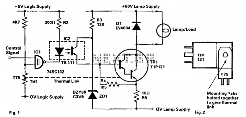
This circuit is designed to drive filament lamps with a nominal rating of 200 mA at 60 V DC using a CMOS logic signal. The lamp or load is connected in series with the Darlington transistor TR1 and an...
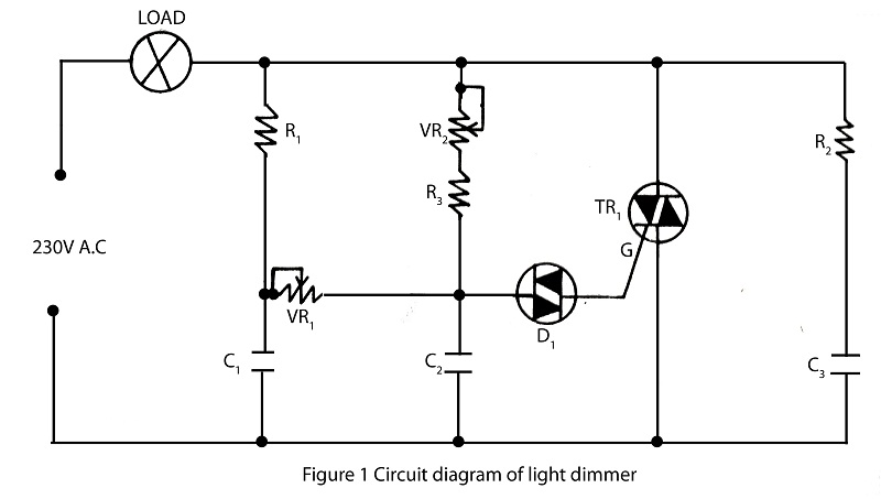
A dimmer is a simple device used to reduce the brightness of incandescent lamps and to control the speed of collector motors. This concept has gained popularity due to the abundance of outdated Soviet circuits available on Lithuanian internet...
A circuit was discovered in a computer, and there is uncertainty regarding its origin and functionality. The main inquiry is whether this circuit can effectively dim 220V LED bulbs. The circuit in question likely utilizes a phase control method for...

This circuit automatically activates a night lamp when the bedroom light is turned off. The lamp stays illuminated until the light sensor detects daylight in the morning. A super-bright white LED is utilized as the night lamp, providing bright...