
Light Dimmer Using Diac or transistor and triac and description

The light dimmer circuit operates by manipulating the phase of the AC voltage supplied to the lighting source. This is achieved through the use of a DIAC, which remains in an off state until a certain voltage threshold is reached. When the voltage across the DIAC exceeds this threshold, it switches on, allowing current to flow through the light source. The variable resistor VR2 adjusts the amount of time the AC waveform is allowed to pass through to the load, effectively controlling the brightness of the light.
In this configuration, capacitor C2 plays a crucial role in determining the timing of the DIAC's triggering. As the capacitor charges, it accumulates voltage until it reaches the breakdown voltage of the DIAC. This process can be influenced by the resistance set by VR2, allowing for a wide range of brightness adjustments. The fine-tuning of brightness is facilitated by VR1, which adjusts the voltage level that the DIAC requires to turn on, enabling precise control over the light output.
Additionally, R2 and C3 are included in the circuit to address potential interference that may arise from the switching action of the DIAC. R2 helps to stabilize the circuit by providing a discharge path for the capacitor, while C3 acts as a filter to smooth out any voltage spikes that could affect the performance of the dimmer.
Overall, this light dimmer circuit exemplifies a practical approach to controlling lighting levels without the need for changing the light source itself, utilizing basic electronic components to achieve the desired functionality.The lighting source (i. e. bulb, tube light) glow according to their specified watt rating. If we need more light then we have to use high watt bulb at the same place if we need low light we have to replace high watt bulb with low rating. But What if there is not necessary to change i. e. different brightness obtained from same source. Here is the s imple but effective project which control brightness according to our use from the unchanged light source. The basic principle of light dimmer is based on phase control. The variable resistor VR2 is main controller of the circuit Light Dimer. From main supply capacitor C2 get charges which trigger DIAC D1. VR1 is used for fine brightness controller which control brightness to lower level. R2 and C3 used to overcome interference problem. 🔗 External reference
Related Circuits
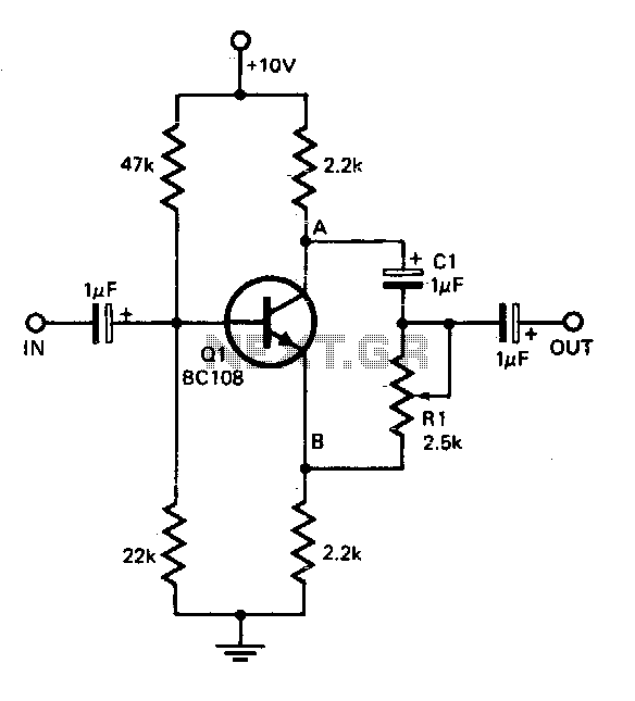
This circuit offers a straightforward method for achieving phase shifts between 0° and 170°. The transistor functions as a phase splitter, with the output at point A being 180° out of phase with the input. Point B remains in...

The circuit below demonstrates the generation of a single positive pulse that is delayed in relation to the trigger input time. It is similar to a previously described circuit but utilizes two stages, allowing for control over both the...
A five-band graphic equalizer utilizing a single integrated circuit (IC). The BA3812L is a five-point graphic equalizer that incorporates all necessary functions within its design. The BA3812L is an integrated circuit specifically designed for audio applications, particularly for graphic equalization...
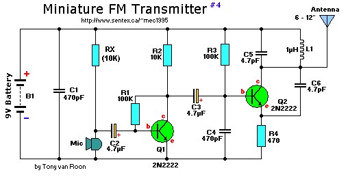
This is a mini FM transmitter designed by Tony van Roon, powered by two transistors. It is straightforward to assemble, and its transmissions can be received on any standard FM radio. The transmitter has an approximate range of 1/4...
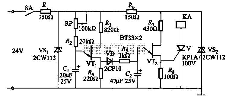
This circuit consists of three single-junction transistor time relay circuits utilizing a pulse charging mechanism, allowing for extended delay times of up to several minutes. The first stage delay circuit incorporates unijunction transistors (VTi) and other components, where capacitor...
This circuit diagram illustrates a triangular wave generating circuit utilizing a pair of operational amplifiers (Op-Amps). The LM741 Op-Amp is recommended for this application. The first Op-Amp, located on the left, functions as a comparator, while the second Op-Amp...