
Zero Crossing Detector (ZCD): Comparator circuit using 741 op amp
%2Busing%2Bop%2Bamp%2B741%2Bic%2B.png)
The zero crossing detector (ZCD) circuit is primarily designed to identify the point where an alternating current (AC) signal crosses the zero voltage level. This is crucial in various applications, including phase-locked loops, motor control systems, and signal processing. The circuit typically employs an operational amplifier (op-amp) configured as a comparator. The op-amp compares the input AC signal with a reference voltage, usually set to zero volts. When the input signal exceeds this reference voltage, the output of the op-amp switches to its positive saturation voltage (+Vsat), and when the input signal falls below the reference, the output switches to its negative saturation voltage (-Vsat).
In the case of the inverting zero crossing detector using the op-amp 741, the non-inverting input is connected to the ground (0V), while the inverting input receives the input signal. The output of the op-amp will toggle between +Vsat and -Vsat based on the input signal's polarity. The circuit can be visualized with a simple schematic that includes the op-amp, resistors for feedback and input, and the output connected to an indicator or another control circuit.
This configuration is beneficial for signal conditioning, where the ZCD can clean up noisy signals by providing a clean square wave output that can be easily processed by digital circuits. Furthermore, the ZCD can be employed in applications such as frequency counters, where it detects the frequency of an input signal by counting the number of zero crossings in a given time frame. In power electronics, it serves as a critical component for switching applications, allowing for precise control of power devices based on the input signal's characteristics.
In summary, the zero crossing detector is an essential circuit in both analog and digital electronics, providing a reliable means of detecting signal transitions and enabling various applications ranging from signal processing to power control.Zero crossing detector(ZCD) is a voltage comparator that switches the output between +Vsat and Vsat (Vsat: Saturation voltage almost equal to 14V) when the input crosses zero reference voltage. Then what is a comparator In simple words comparators are basic operational amplifier circuits that compare two voltages simultaneously and switches th
e output according to the comparison. We can say zero crossing detection circuit is a comparator example. We will discuss in detail about comparator in our upcoming articles. Inverting zero cross detector circuit schematic using op amp 741 IC is shown below along with working, input output wave forms. ZCD circuit can be used to check whether the op-amp is in good condition. Zero crossing detectors can be used as frequency counters and for switching purposes in power electronics circuits.
ZCD is a basic op amp circuit. 🔗 External reference
Related Circuits
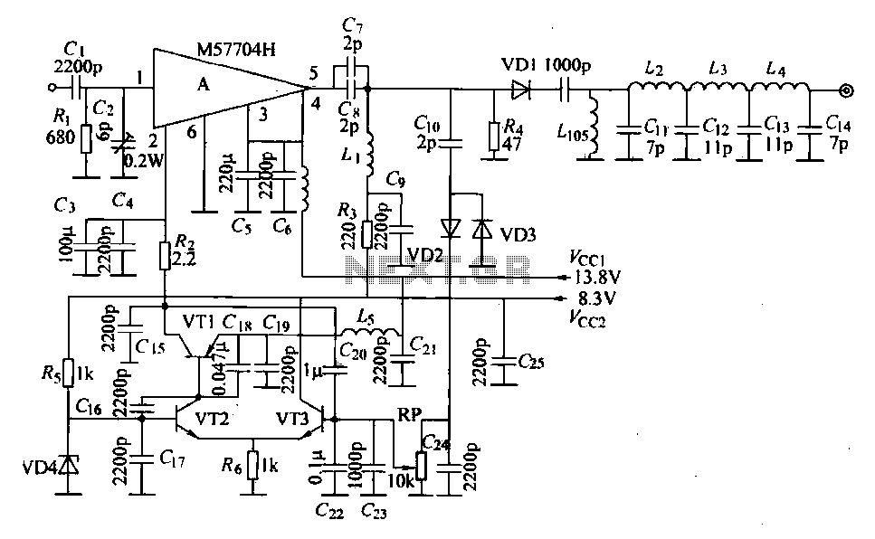
The FM radio transmitter is a high-frequency amplifier circuit that utilizes the Mitsubishi frequency set, specifically the M57704H discharge path. It operates within the frequency range of 457-458 MHz and has a transmission power of 5 watts. As illustrated...
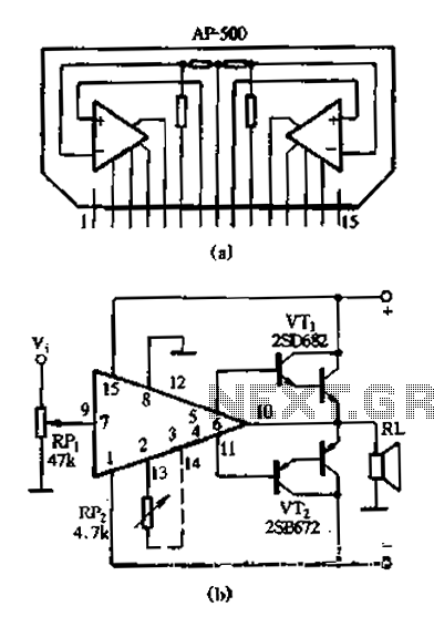
The AP500 is a high-performance dual-channel FET DC amplifier driver module designed for high operating voltage applications. It features push power, low distortion, a wide frequency response, and a simple external circuit. Utilizing superior resistance characteristics in audio circuits,...
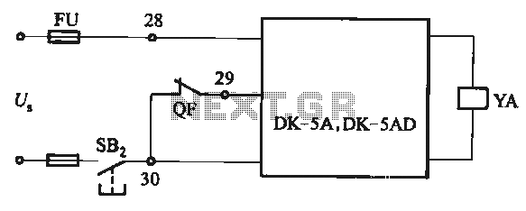
The DK-5A and DK-5AD AC power control circuit is illustrated in Figure 6-77. The figure includes a closing button (SBz) and a line (YA) connected to the closing electromagnet coil (U). This circuit is designed for the operation of...
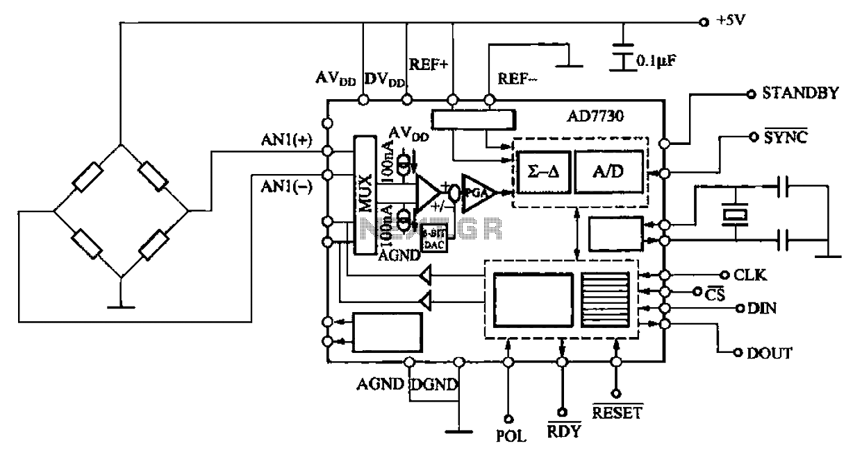
AD7710/7715/7730 multifunction digital sensor signal conditioning integrated circuits (ICs) that combine a digital interface with a control port, a clock generator, a digital filter, amplitude modulation, a programmable gain amplifier, an analog-to-digital (A/D) converter, and additional electrical pathways. The...
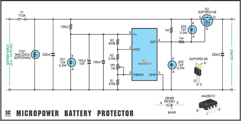
Protect expensive batteries from discharge damage with this mini-sized electronic cutout switch. It uses virtually no power and can be built to suit a wide range of battery voltages. The mini-sized electronic cutout switch serves as a crucial component in...
This is a directly coupled (DC) amplifier circuit. It is constructed using NPN and PNP transistors and is designed to amplify direct current (DC) signals. The directly coupled amplifier circuit utilizes both NPN and PNP transistors to achieve its amplification....
Warning: include(partials/cookie-banner.php): Failed to open stream: Permission denied in /var/www/html/nextgr/view-circuit.php on line 713
Warning: include(): Failed opening 'partials/cookie-banner.php' for inclusion (include_path='.:/usr/share/php') in /var/www/html/nextgr/view-circuit.php on line 713