
dc motor control avr atmega8
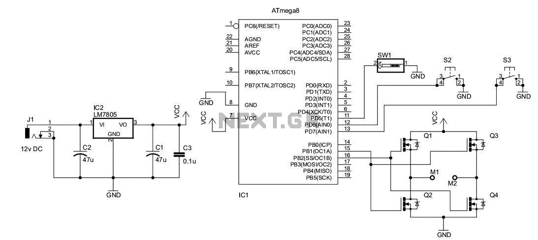
The circuit design utilizes a DC motor, which is a common component in various applications due to its simplicity and effectiveness. The H-bridge configuration is fundamental in enabling bidirectional control of the motor. The H-bridge consists of four MOSFETs arranged in a bridge configuration, allowing for the reversal of current through the motor by switching the active pairs of MOSFETs based on the PWM signals received.
The PWM (Pulse Width Modulation) technique is employed to control the speed of the motor by varying the duty cycle of the PWM signals. A higher duty cycle corresponds to a higher average voltage across the motor, leading to increased speed, while a lower duty cycle decreases the speed. The active PWM channel determines which pair of MOSFETs is conducting, thereby controlling the flow of current and the direction of the motor.
The Direction Control switch plays a critical role in this circuit. When toggled, it changes the active PWM channel, which in turn activates the opposite pair of MOSFETs. This switching mechanism allows for seamless direction changes in the motor's operation, providing flexibility in applications where the motor needs to reverse its rotation.
In summary, this circuit effectively harnesses the properties of PWM and H-bridge configurations to achieve precise control over the speed and direction of a DC motor, making it suitable for various robotics and automation projects. Proper component selection, including the MOSFET ratings and PWM frequency, is essential to ensure efficient operation and longevity of the circuit.I had used a DC motor from an old personal stereo cassette player. The circuit provides speed and direction control of the motor. The PWM waveforms are used for driving the MOSFET H-bridge as shown in the schematic: At a time only one of the two PWM channel is active, driving only two MOSFETS (either Q1-Q4 or Q3-Q2). Other two MOSFETs remain OFF. Whenever the Direction Control switch is toggled, the PWM channel is also changed, driving the alternative pair of MOSFET, which changes the direction of current flow through motor, resulting in the direction change in rotation of motor shaft. 🔗 External reference
Related Circuits
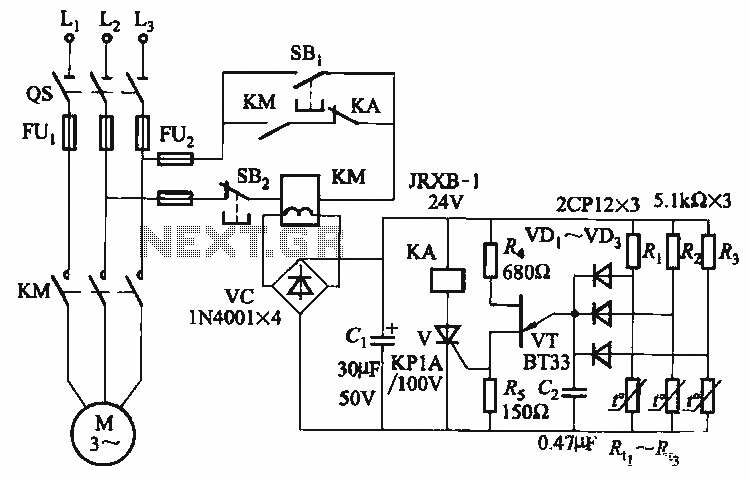
The thyristor control circuit includes a bridge circuit designed to regulate the temperature in the contactor coil KM, along with a secondary winding that functions as a power protection device. It comprises a thermistor (R:., Rt3) and a resistor...
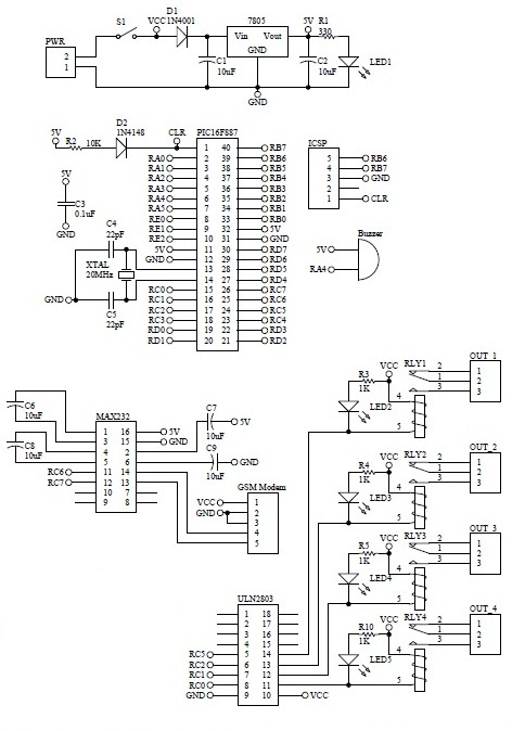
How to turn on equipment by sending SMS `1111` to switch it ON and switch off the equipment by sending SMS `0000`. The GSM switch will receive instructions for either load 1 (L1), load 2 (L2), load 3 (L3),...

Many times, code has been written for UART communication, but testing was hindered by the absence of a serial port on the laptop. A USB to serial port converter was purchased, but it did not function as expected. Frustration...
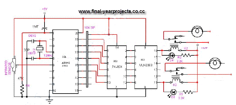
This is a comprehensive electrical project report on an Infrared Remote Control On/Off Switch, submitted to fulfill the requirements for the Bachelor of Engineering degree in Electrical Engineering. The project is designed to control the operation of home appliances...
Battery-powered devices, such as electric toothbrushes, shavers, cell phones, PDAs, MP3 players, and remote controls, are integral to daily life. Consequently, power management has become a critical consideration for embedded designers. Microcontrollers (MCUs) provide various methods for managing power...
This is a high quality power supply with a continuously variable stabilised output adjustable at any value between 0 and 30VDC. The circuit also incorporates an electronic output current limiter that effectively controls the output current from a few...
Warning: include(partials/cookie-banner.php): Failed to open stream: Permission denied in /var/www/html/nextgr/view-circuit.php on line 713
Warning: include(): Failed opening 'partials/cookie-banner.php' for inclusion (include_path='.:/usr/share/php') in /var/www/html/nextgr/view-circuit.php on line 713