
Programmable Control For Home Safety via GSM Remote
The described system utilizes a GSM switch that allows remote control of multiple electrical loads via SMS commands. The operational commands are simple text messages: sending `1111` activates the desired load, while sending `0000` deactivates it. The system can manage four distinct loads, identified as Load 1 (L1), Load 2 (L2), Load 3 (L3), and Load 4 (L4).
The GSM switch is equipped with a GSM module that receives SMS messages sent from a mobile phone. Upon receiving a command, the module decodes the message and determines which load to control based on the specified command. Each load is connected to a relay that acts as a switch, allowing or interrupting the flow of electricity to the load.
The status of each load is monitored and reported back to the user. After processing the commands, the GSM switch sends SMS notifications indicating whether each load is currently ON or OFF. This feedback mechanism ensures that the user is informed of the operational state of their equipment.
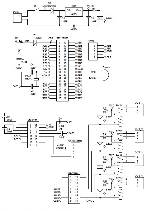
The schematic for this system would typically include the following components: a GSM module, microcontroller (such as an Arduino or PIC), relays for each load, power supply circuits, and necessary protective components like diodes and fuses. The GSM module connects to the microcontroller, which interprets the incoming SMS commands and activates the appropriate relay to control the associated load. Each relay output connects to the respective load, allowing for safe operation of the electrical devices.
Overall, this GSM switch system provides a convenient and efficient method for controlling electrical equipment remotely, enhancing user accessibility and operational flexibility.How to turn on equipment by sending SMS `1111` ON `and switch off the equipment by sending SMS` 0000 GSM Switch will receive instructions either load 1 (L1), load 2 (L2), load 3 (L3) or load 4 (L4). Then the GSM Switch will send the four load status is ONor OFF either. Skematiknya are as follows 🔗 External reference
Related Circuits
This circuit demonstrates that microprocessors, PCs, and modern ultra-accurate Digital-to-Analog Converters (DACs) are excessive for controlling four relays in sequence based on a control voltage ranging from 2.4 V to 12 V. By utilizing equal resistors in a ladder...
Beeper and/or LED remotely-operated via mains supply line. Pressing the pushbutton of the transmitter, a sound and/or light alert is activated in the receiver. The system uses no wiring or radio frequencies: the transmitted signal is conveyed into the...
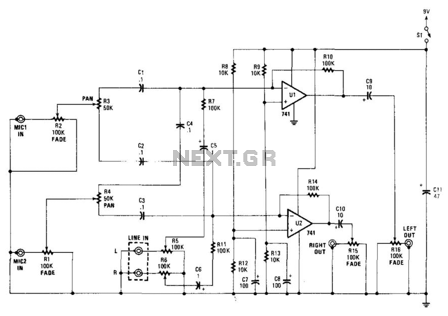
This stereo mixer features two mono mixers and a modification to the microphone inputs. When a microphone is in use, its output is directed to the microphone input of the circuit. The signal is then processed through resistors R1...
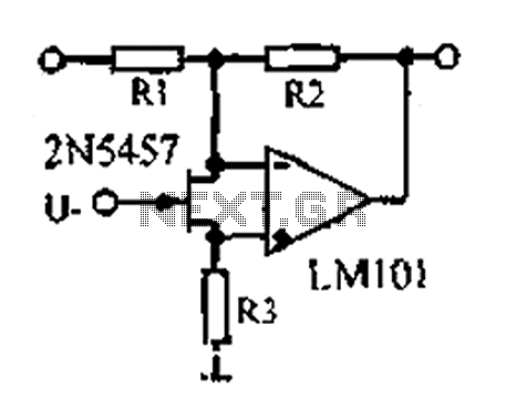
A 1.53 voltage-controlled gain amplifier (VGA) utilizes a FET connected between the two inputs of the operational amplifier (op-amp) as a voltage-controlled resistance. The resistance changes linearly with voltage and varies from several dozen square ohms, exhibiting excellent control...
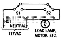
This switching arrangement is utilized in both domestic and industrial environments to enable control of a light or other AC-operated device from multiple locations. This switching arrangement, commonly referred to as a multi-way switching system, is designed to facilitate the...
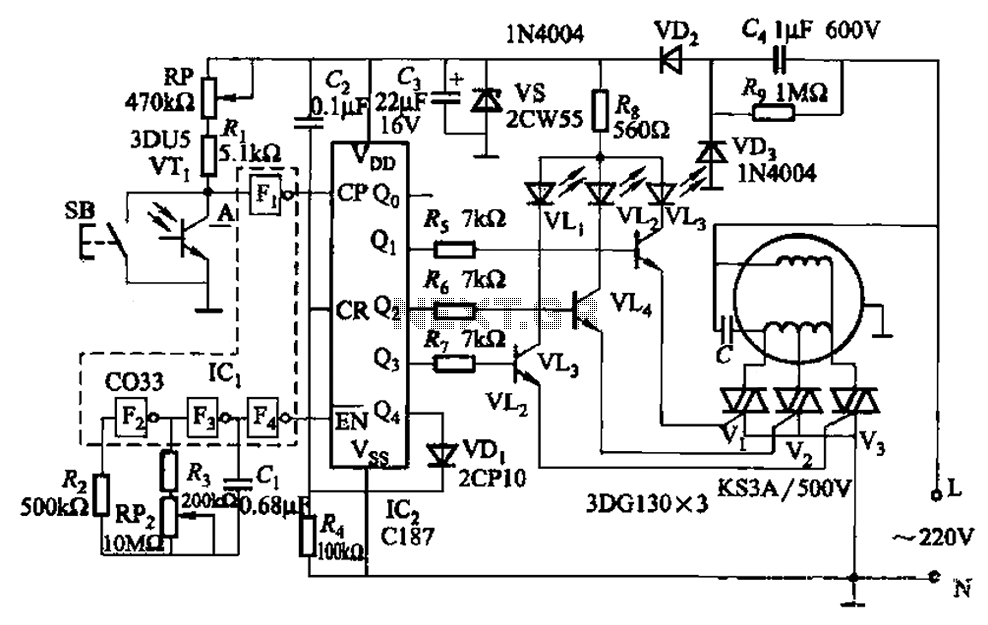
The circuit depicted in Figure 3-5 can be controlled manually using button SB or automatically via light detection using phototransistor VTj. When light from a flashlight is detected by phototransistor VTj, the fan will activate, adjusting its speed automatically...