
DC Motor Control System Block Diagram
The two-quadrant controller schematic operates by integrating both speed and current control loops to maintain precise motor operation. The outer speed control loop, utilizing feedback from the tachogenerator, ensures that the motor speed adheres to a predefined reference. The inner current control loop is critical for maintaining safe operational limits, preventing overcurrent situations that could damage the motor or associated circuitry. The inclusion of a current limit setting is essential for safeguarding against unexpected spikes in current demand, particularly during rapid changes in speed.
The system's ability to detect motoring versus regenerating states enhances its versatility, allowing for efficient energy recovery during braking scenarios. The hysteresis implemented in the logic circuit aids in stabilizing the control action, minimizing the risk of rapid switching between states that could lead to inefficiencies or instability.
The comparison of actual motor current with the reference signal within a defined tolerance band allows for a responsive control strategy. In scenarios where the motor current exceeds the established limits, the output comparator's intervention ensures that the power MOSFET is temporarily turned off, thereby enabling the current to decrease safely. This method not only protects the hardware but also optimizes performance by allowing for controlled current freewheeling.
The choice between variable effective switching frequency and fixed PWM frequency provides flexibility in design, catering to different application requirements. The PWM method's use of a triangular wave for comparison with the current error signal ensures consistent and reliable switching behavior, crucial for maintaining the desired operational characteristics of the motor.
Overall, this two-quadrant controller schematic is designed to deliver efficient motor control with robust safety features, making it suitable for a wide range of applications in automation and robotics.A schematic arrangement for a two quadrant controller is shown on figure below. This figure show us the outer speed control loop and the inner current control loop. The tachogenerator derive the speed feedback signal, although alternatively an approximation to the motor speed can be derived by feeding back a signal proportional to the motor voltag e, (AVF). For servo applications, position feedback can be included by using a position encoder on the motor shaft. The tacho- output voltage is compared with a speed reference signal by the feed feedback loop. The current reference command is given by the voltage error signal. In the inner control loop, the current command signal is compared with the actual motor current. A current limit setting which protects the motor and the devices from overcurrents is included in this control loop.
The current demand is maintained below the maximum level by this current limit setting if the controller demands a large speed change. Motoring or regenerating operation is detected directly from the polarity of the voltage error signal.
This will be used to determine whether it is the top or bottom MOSFET which is controlling the current. To ensure that control does not oscillate between the motoring and regenerating modest low motor currents, the motoring/regenerating logic circuit includes some hysteresis.
By controlling the switching sequences to the main PowerMOS devices, there are several possible ways of controlling motor current. The motor current is compared with the reference signal and allowed current ripple tolerance in tolerance band control.
If the actual current is greater than the allowed maximum value of the tolerance band during motoring operation, then the output comparator turns off the gate drive to the power MOSFET thus allowing the motor current to fall. Then, when the comparator turns the MOSFET back on, the current freewheels until it reaches the lower limit of the tolerance band.
The effective switching frequency is variable if we using this current control strategy. It`s all depending on the rate at which the armature current changes, but the peak to peak current ripple in the system is constant. Alternatively, using a PWM method current control, the devices can be switched a constant frequency. The current error signal is compared with a fixed frequency triangular wave. Then the output of the comparator is used to provide the signal for the main switching devices. The power device is switched on when the error signal is greater than the triangular wave and the device is switched off when the error signal is less than the triangular carrier.
[Block diagram source: nxp. com] We aim to transmit more information by carrying articles. Please send us an E-mail to wanghuali@hqew. net within 15 days if we are involved in the problems of article content, copyright or other problems. We will delete it soon. 🔗 External reference
Related Circuits
A photo-activated normally open relay is employed in a circuit that interacts with light. In this configuration, a photodiode is utilized to detect light levels. The photodiode exhibits high resistance in the absence of light. It is connected in...
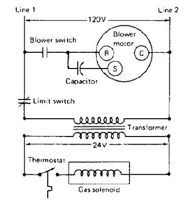
The gas furnace is the simplest to operate and understand. Therefore, it will be used here to examine a typical heating system. This type of natural gas furnace is utilized to heat millions of homes in the United States....
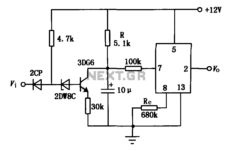
The delay application circuit is depicted in Figure JEC-2, which consists of two components. When the input transitions from logic level 0 to 1, the output also changes to 1 immediately. However, when the input transitions from high level...
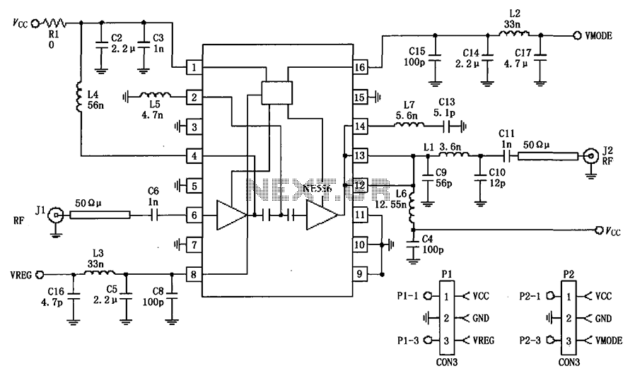
The circuit depicted in the figure is a 380MHz RF2175 linear amplifier application circuit. The radio frequency (RF) signal is input from pin 6 and is processed through a preamplifier, followed by a final power amplifier stage. The output...
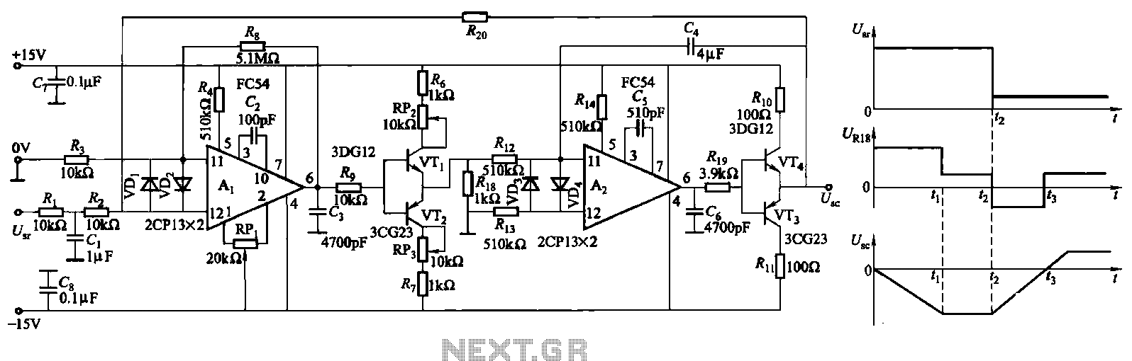
The ZKJ-S-type buffer controller circuit is designed for motor starting slip control. This buffer controller is composed of two operational amplifiers, Ai and Az. The operational amplifier Ai functions as a speed amplifier that saturates, while Az acts as...
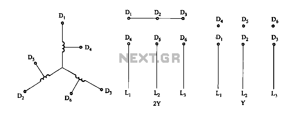
Figure 3-100 illustrates the lead wiring diagram for the stator windings of a two-speed motor configured in a 2Y/Y connection. The two-speed motor stator wiring diagram depicted in Figure 3-100 provides a clear representation of the electrical connections required for...