
Two-speed motor stator winding 2Y-Y connection
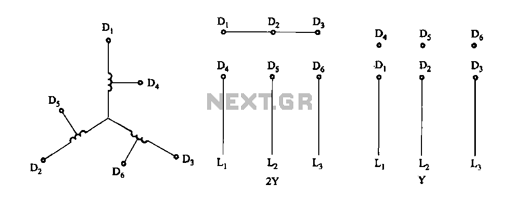
The two-speed motor stator wiring diagram depicted in Figure 3-100 provides a clear representation of the electrical connections required for the operation of a two-speed induction motor. The 2Y/Y connection indicates that the motor windings are connected in a wye configuration, which is essential for enabling the motor to operate at two different speeds.
In this configuration, the stator windings are divided into two sets, allowing for the selection of different voltage levels depending on the desired speed. The diagram typically includes labels for each winding, as well as the corresponding lead connections that facilitate the switching between high and low-speed operations.
The 2Y/Y connection is advantageous because it allows for reduced starting currents and improved efficiency during operation. The diagram may also illustrate the use of contactors or relays that are employed to switch between the two speed settings. Proper understanding and implementation of this wiring diagram are crucial for ensuring the motor operates effectively and reliably in its intended application.
In summary, Figure 3-100 serves as a vital reference for engineers and technicians involved in the installation, maintenance, and troubleshooting of two-speed motors, providing essential information on the connections and configurations necessary for optimal performance.Fig. 3-100 is a two-speed motor stator windings lead wiring diagram 2Y/Y-connected.
Related Circuits

This is an easy to build stepper motor driver that will allow you to precisely control a unipolar stepper motor through your computer's parallel port. With a stepper motor you can build a lot of interesting gadgets such as...
A closed-loop or servo system has the capability to stabilize the controlled plant at a specified operating condition. The plant, which is the controlled sub-system, can be... A closed-loop control system, commonly referred to as a servo system, is designed...
Correctly adjusted, the voltage on the pot wiper is slightly less than half D+ (appx. 0.47*D+) and Q1 will conduct if (D+)-(Vp) > 6.2 + 0.7 + 0.7, or 0.53*(D+) > 7.6V, (D+) > 14.3V. If D+ is lower...
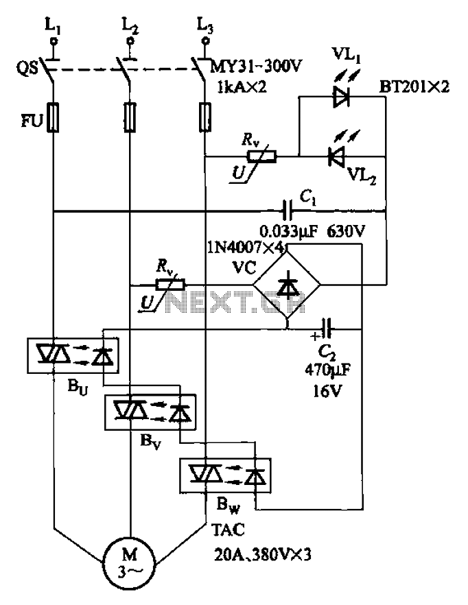
The circuit depicted in Figure 3-93 is integrated with an optical phase sequence protection relay. The circuit in question is designed to provide phase sequence protection using an optical relay mechanism. Optical phase sequence protection relays are crucial in applications...
It's basically a photovore with a couple tactile sensors. It's rather complex but can give neat behaviors with modifications to the circuit. At this point I don't have any plans to give more information on this circuit so your...
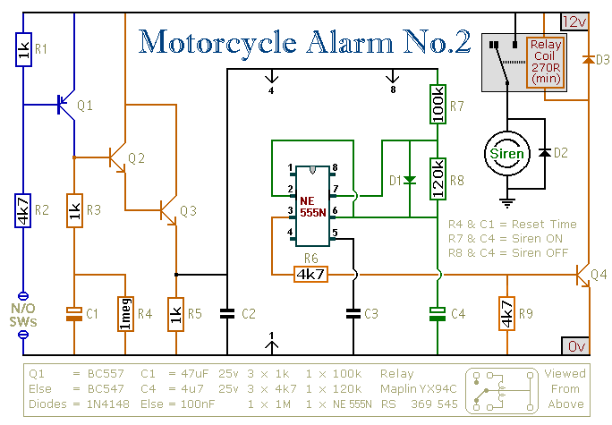
This circuit features an intermittent siren output and automatic reset. It can be operated manually using a key switch or a hidden switch; however, it can also be wired to activate automatically when the ignition is turned off. By...
Warning: include(partials/cookie-banner.php): Failed to open stream: Permission denied in /var/www/html/nextgr/view-circuit.php on line 713
Warning: include(): Failed opening 'partials/cookie-banner.php' for inclusion (include_path='.:/usr/share/php') in /var/www/html/nextgr/view-circuit.php on line 713