
joule savercircuit
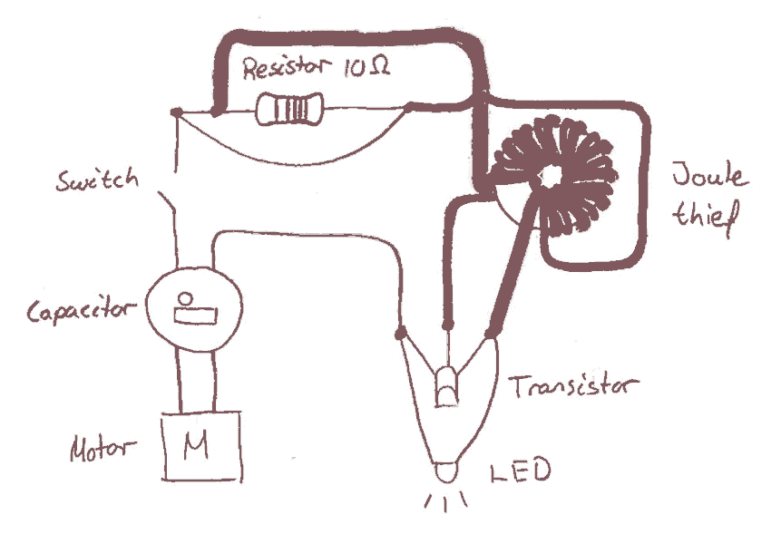
The circuit design incorporates a joule saver mechanism aimed at enhancing the operational efficiency of the LED lighting system. The primary component, a capacitor, serves as an energy storage element that captures excess energy generated while the handle is being turned. This stored energy can then be released to power the LED light, ensuring it remains illuminated for a brief period after the handle stops turning.
In this configuration, the capacitor is connected in parallel with the LED. When the handle is turned, the dynamo generates electrical energy, which charges the capacitor. The charging process continues until the handle is released, at which point the capacitor discharges its stored energy to the LED. This results in a sustained light output, providing a visual indication even after the mechanical input has ceased.
To optimize performance, it is essential to select a capacitor with an appropriate capacitance value, taking into account the LED's voltage and current requirements. Additionally, a diode may be included in the circuit to prevent backflow of current, ensuring that the capacitor only discharges to the LED and not back to the power source.
The overall schematic should include the dynamo, a switch (if necessary), the capacitor, the LED, and the diode, clearly indicating the connections and polarity where applicable. This design not only improves user experience by extending the LED's illumination time but also contributes to energy efficiency by utilizing stored energy effectively.Already early in the process regarding the electronics we thought it could be useful to implement a joule saverin thecircuit. The intention using a joule saver is to keep the LED light even after stopping turning the handle. Therefore we chosen to incorporate a capacitor in the circuit. 🔗 External reference
Related Circuits

A series of LEDs that turn on and off in a precise sequence, creating a calming and hypnotic effect. Various LED chaser, scanner, and sequencer circuits exist, utilizing discrete transistors, logic integrated circuits (ICs), or microcontrollers. However, a common...
D1 (Schottky diode) and C2 form a rectifier to create DC voltage from the Joule Thief. A Zener diode D2 is included to limit the voltage to 5.1V, preventing damage to the microcontroller, which has a maximum voltage tolerance...
This project involves a flashlight design that incorporates a joule thief circuit. The flashlight utilizes a pen-style body from Duracell, featuring a 2.2-volt lamp powered by two AAA batteries. The original lamp will be replaced with a 5 mm...
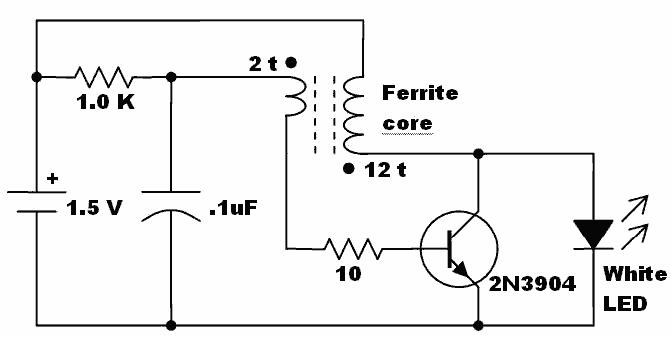
Here is an idea for a voltage booster that enables the lighting of a white LED using a single AA cell. This presents an opportunity to utilize one of the ferrite cores and white LED holiday lights mentioned in...
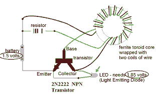
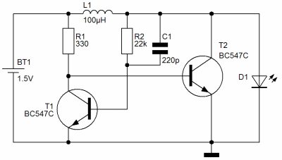
This circuit is known as the Joule Thief. For those unfamiliar with it, an image of the circuit is provided. The Joule Thief is a minimalist circuit designed to extract usable voltage from a low-voltage power source, such as a...
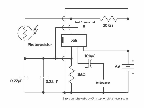
A light Theremin constructed using an oscilloscope panel, enhanced with a Joule Thief circuit. The design incorporates a 10 K variable resistor for pitch control and a 20 K variable resistor for volume control. The circuit is powered by...