
DC Motor Controller
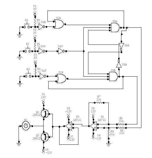
The described DC Motor Controller circuit is designed to manage the operation of a 12V DC motor through a user interface comprising three pushbuttons: START, REVERSE, and STOP. The circuit operates under specific conditions that govern the motor's directional control and stopping mechanisms.
Initially, the circuit maintains the motor in a non-operational state. Upon pressing the START button, the motor is activated and begins to rotate in a predetermined direction, which can be defined by the circuit configuration. The implementation of this functionality typically involves a relay or an H-bridge driver, which allows for the control of the motor's direction and power.
While the motor is in operation, pressing the REVERSE button has no effect, thereby preventing any unintended direction changes during active operation. This feature is critical for applications requiring consistent motor performance without interruption. The STOP button serves as an emergency or standard halt mechanism, immediately ceasing motor operation regardless of the current state.
In the event that the motor is stopped, pressing the REVERSE button will initiate the motor's operation in the opposite direction, effectively allowing for a change in direction only when the motor is not actively running. Conversely, if the motor is running in the REVERSE direction, pressing the START button will not alter its operation.
The circuit can be implemented using basic electronic components such as transistors, diodes, and resistors, alongside the pushbuttons for user input. Additional features such as indicator LEDs may be included to signal the current state of the motor (running, stopped, or reversing). Proper power supply considerations for the 12V motor and the control circuit must also be taken into account to ensure reliable operation.This DC Motor Controller circuit will control a 12V dc motor. The system will have three pushbuttons: a START button, a REVERSE button and a STOP button. Initially, the motor must not be running. When the START button is pressed, the motor will run in one direction. Pressing the REVERSE button (while the motor is running in START direction) must have no effect on the motor. Pressing the STOP button must stop the motor from running. Pressing the REVERSE button while the motor is stopped will make the motor run in a direction (opposite to the direction for the START button). Pressing the START button (while the motor is running in REVERSE direction) must have no effect on the motor.
P 🔗 External reference
Related Circuits
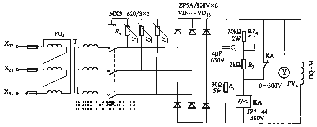
FIG T is the excitation transformer, R is a varistor, and there are rectifier diodes to protect against breakdowns from VDii to VD16; Rz and C2 provide resistive-capacitive protection. The circuit is designed to absorb voltage from the magnetic...
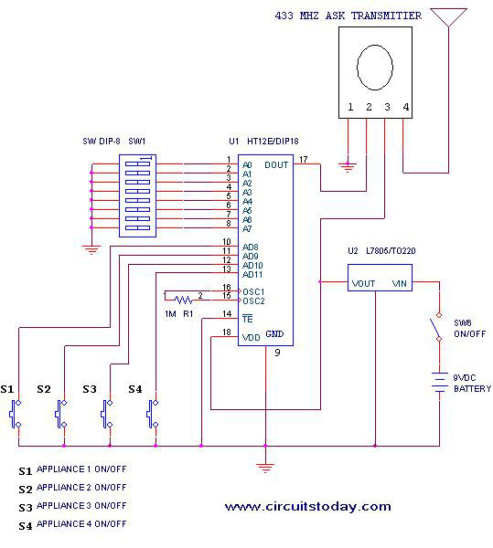
This project outlines a simple remote control system utilizing RF communication without the use of a microcontroller. The remote is designed for various home appliances such as televisions, fans, and lights, providing significant convenience by allowing operation from a...
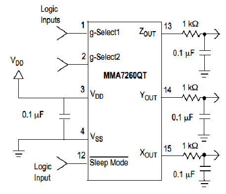
Microcontroller-Based Accelerometer Project. Just as a speedometer is a device that measures speed, an accelerometer is a device that measures acceleration. The microcontroller-based accelerometer project utilizes an accelerometer sensor to detect changes in velocity and orientation. This project typically involves...
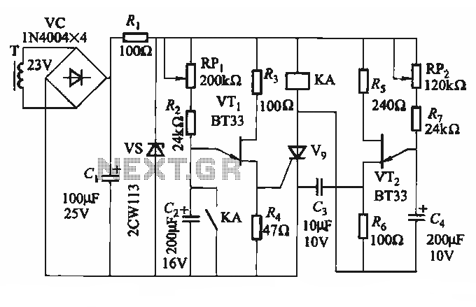
The circuit depicted in Figure 3-69 is designed for applications requiring frequent timing control for motor reversing operations. In this configuration, thyristors V1, V2, and V7 are utilized for positive control of motor rotation, while thyristors V3, V4, V5,...
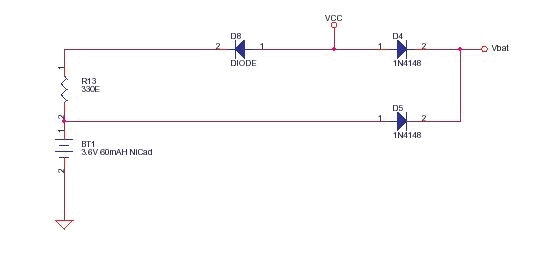
This circuit functions as a low-cost battery backup solution for SRAM and microcontroller/microprocessor applications. It utilizes 1N4148 diodes to prevent battery discharge back to the power source. Diode D8 provides a one-way path for charging the battery through resistor...
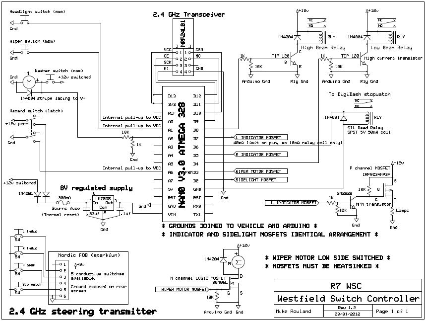
The core of the switch controller is an Arduino Nano microcontroller, which will serve as the interface between the dashboard switches, wireless steering wheel buttons, and the vehicle's lighting, indicators, windscreen wipers, and DigiDash2 GPS stopwatch. This setup facilitates...