
DC motor excitation current circuit
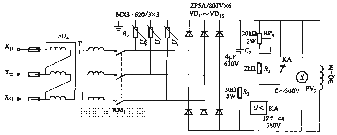
The described circuit involves an excitation transformer (T) that plays a critical role in supplying the necessary voltage to the DC motor (M) while ensuring operational safety. The varistor (R) is strategically placed to clamp voltage surges, thus protecting the circuit from transient overvoltages. The inclusion of rectifier diodes further enhances protection by preventing reverse current flow, which could lead to component failure. The specific breakdown voltage range from VDii to VD16 indicates that these diodes are selected based on their voltage ratings to match the operational parameters of the circuit.
The resistive-capacitive protection provided by Rz and C2 serves to filter out high-frequency noise and stabilize the voltage across the excitation transformer, ensuring that the motor operates smoothly without interference from electromagnetic interference (EMI) or other transient disturbances.
The circuit's capability to absorb voltage from the magnetic field side is crucial for maintaining the integrity of the system, especially in scenarios where magnetic field fluctuations could induce unwanted voltages. The KA magnetic field loss of pressure relay is an essential safety feature that monitors the magnetic field's integrity and activates protective measures if a loss is detected, preventing potential damage to the DC motor (M) from magnetic coaster accidents.
Finally, the BQ-M designation for the excitation windings of the DC motor (M) indicates the specific configuration and characteristics of these windings, which are designed to ensure efficient operation while minimizing losses. Overall, this circuit design reflects a comprehensive approach to safeguarding the operation of the DC motor in the presence of magnetic field disturbances, ensuring reliability and longevity in its application.FIG, T is the excitation transformer, R, varistor, rectifier diodes to protect against VDii ~ VD16 breakdown; Rz, C2 resistive capacitor protection circuit to absorb the magnetic field-side voltage; KA magnetic field loss of pressure relay Electric to avoid DC motor M due to loss caused by magnetic coaster accidents; BQ-M DC motor M excitation windings.
Related Circuits
Electronics tutorial about DC motors, electrical motors, and stepper motors used as actuators, including PWM and transistor H-bridge motor control. DC motors, electrical motors, and stepper motors are integral components in various applications, functioning as actuators to convert electrical energy...
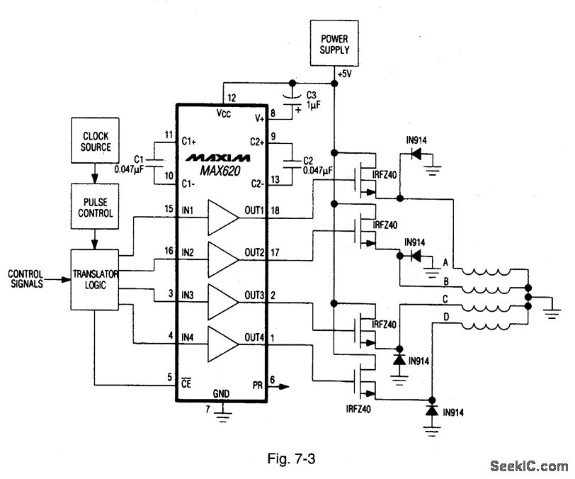
A MAX620 is connected to create a complete stepper motor drive system. TTL/CMOS signals from the logic network are converted to high-side levels that control four N-channel power MOSFETs, which supply current to each of the four phases of...
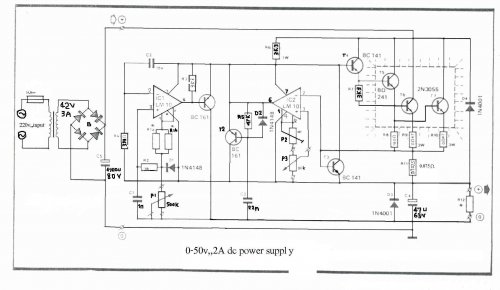
The LM10 integrated circuit (IC) is utilized due to its reference voltage feature, which is advantageous for DC power supply applications. By employing two LM10 ICs, different output voltages and current levels can be achieved. This circuit includes short-circuit...
The EPSON PHOTO 830U printer power circuit illustrates the power supply circuit for the EPSON PHOTO 830U printer, which operates as a switching power supply. During normal operation, the power supply input socket receives a 220V AC supply to...
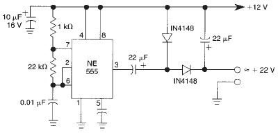
This voltage doubler circuit utilizes a 555 timer integrated circuit configured as an astable multivibrator. It can deliver a maximum output current of 50mA; exceeding this limit will result in a reduction of the output voltage. The actual output...
This is a programmable alarm timer circuit that uses LEDs to indicate hours and minutes. Twelve LEDs can be arranged in a circle to represent the 12 hours of a clock face, and an additional 12 LEDs can be...