
DC motor dynamic braking circuit
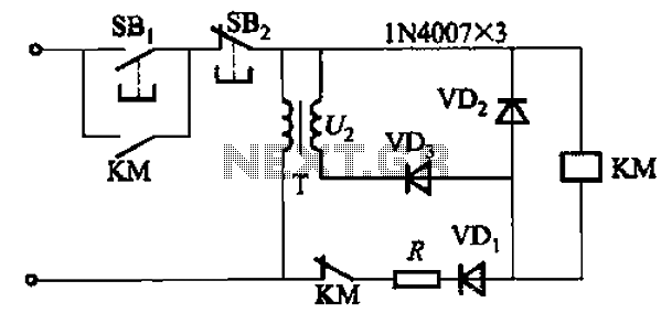
The described dynamic braking circuit for a DC motor utilizes a series of components to effectively manage the motor's stopping process. The circuit begins with the operation of the stop button (SB2), which initiates the braking sequence. Pressing this button results in the deactivation of contactor (KM1), which is crucial for cutting off the supply voltage to the motor. This interruption is essential to prevent further rotation of the motor.
Simultaneously, relay (KV) is activated, closing its contacts to engage the electric brake contactor (KM2). This contactor plays a vital role in connecting a braking resistor (R) across the armature terminals. The inclusion of this resistor is significant as it allows for the dissipation of energy generated during the motor's deceleration. When the excitation current is redirected, the motor generates a braking torque, which aids in rapidly reducing the motor's speed.
As the motor slows down, the back EMF produced by the armature decreases. This back EMF is a critical parameter, as it reflects the motor's speed and the energy being fed back into the circuit. When this back EMF drops below the predetermined release voltage of relay (KV), the relay releases, causing contactor (KM2) to deactivate. This action signifies the end of the braking process, effectively stopping the motor.
The dynamic braking circuit is an efficient method for managing the rapid deceleration of DC motors, ensuring both safety and performance in various applications. Proper understanding and implementation of each component are essential for achieving optimal braking performance.DC motor is shown in dynamic braking circuit. Braking, press the stop button SB2, the contactor KM1 missing, and released its movable contact connected off, electrical voltage relay KV eligible actions, which make contacts closed, the electric brake contactor KM2 eligible action will braking resistor R is connected in parallel at both ends of the armature, then changed direction due to the excitation current, the torque produced by the motor brake torque, the motor stops quickly. When the armature back EMF voltage is lower than the release voltage relay KV, KV release, so KM2 missing, and released the end of the braking process.
Related Circuits
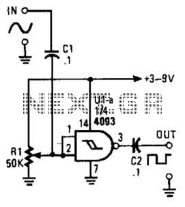
This circuit converts a sine wave into a square wave. It consists of a single 2-input NAND Schmitt trigger configured as an inverter, with an adjustable trigger level at its input. As the input voltage exceeds the gate's trigger...
An AC contactor DC transformer circuit operates as a voltage regulator for AC applications. DC contactors come in various types. AC contactors are electromechanical devices used to control the flow of electrical power in AC circuits. They function by opening...
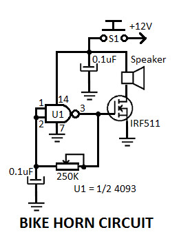
This simple electronic bicycle horn circuit utilizes a single gate from a 4093 quad 2-input NAND Schmitt trigger (U1) connected in a straightforward, low-frequency square wave configuration. The electronic bicycle horn circuit operates by generating a square wave signal that...
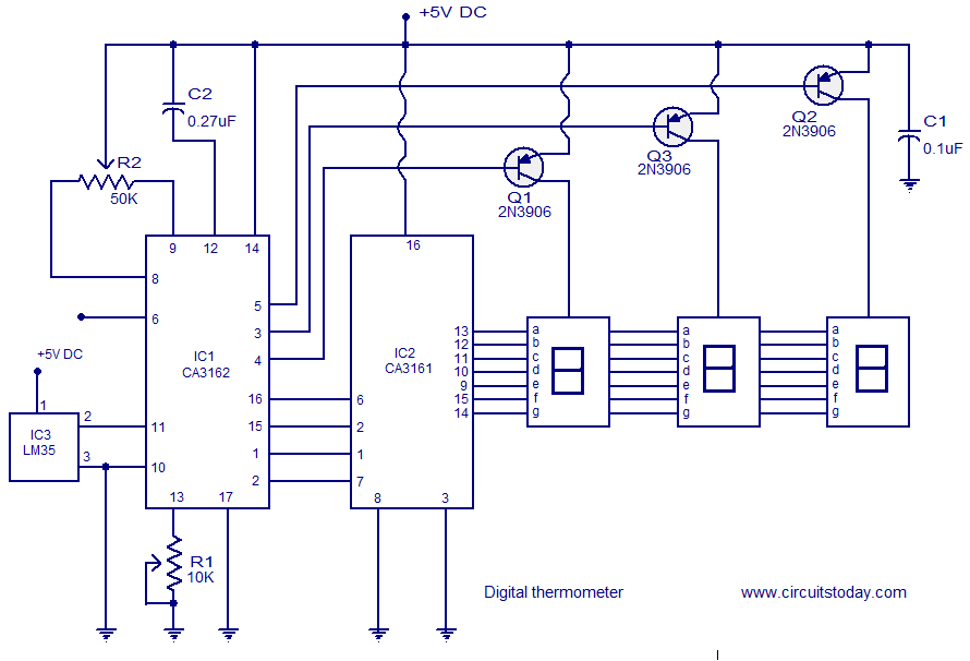
A simple digital thermometer circuit without a microcontroller and featuring a seven-segment LED readout is presented. The circuit utilizes three integrated circuits (ICs): CA3162, CA3161, and LM35. The CA3162 is a monolithic analog-to-digital (A/D) converter with a BCD output....
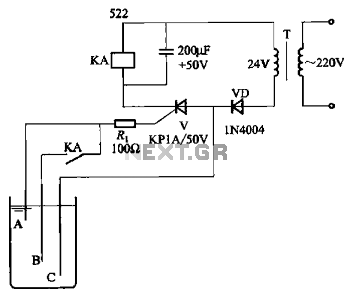
The circuit depicted in Figure 11-14 utilizes a unidirectional thyristor within liquid level automatic control systems. It incorporates electrodes that serve as sensing elements for detecting the level of water or other conductive liquids. The circuit features a current...
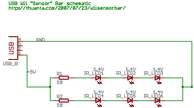
The following circuit illustrates the Wii "Sensor" Bar Project Circuit Diagram. Features include a series of infrared LEDs positioned at both ends of the bar, which emit infrared light. The Wii Sensor Bar is a crucial component for the Wii...