
Sine Wave To Square Wave Converter Circuit
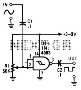
The circuit utilizes a 2-input NAND Schmitt trigger, which is an essential component for signal shaping and noise immunity. The Schmitt trigger is characterized by its hysteresis, meaning it has two distinct threshold voltages: one for transitioning from low to high and another for transitioning from high to low. This feature helps eliminate any noise that may be present in the input sine wave, ensuring a clean square wave output.
In this configuration, the sine wave input is fed into one of the inputs of the NAND gate. The second input is tied to a logic high (Vcc), effectively transforming the NAND gate into a NOT gate. The adjustable trigger level allows for fine-tuning of the input voltage at which the output state changes. When the input sine wave exceeds the upper threshold voltage, the output of the NAND gate switches from high to low, creating a square wave that toggles between these two states.
The output frequency of the square wave is determined by the frequency of the input sine wave. The circuit can be used in various applications, such as signal conditioning, waveform generation, and in digital systems where a square wave is required for clock signals or other timing applications. Proper design considerations, including power supply decoupling and input/output impedance matching, should be taken into account to ensure optimal performance of the circuit. This circuit turns a sine wave into a square wave. It is comprised of a single 2-input NAND Schmitt trigger that`s configured as an inverter with a trigger level adjustment at its input. As the input voltage rises above the gate`s trigger point, the output snaps to its alternate state, producing a square-wave output. 🔗 External reference
Related Circuits
Up to eight players each have their own answer button to press, corresponding to the four Red Team and four Green Team LEDs on the master control board. As soon as the first contestant who thinks they know the...
A simple proximity detector can be created using this electronic circuit. This circuit responds to the presence of a conductive object within a specific range. The sensitivity of the circuit can be adjusted with potentiometer P1 to achieve the...
The circuit illustrated in Figure 2-50 utilizes a field effect tube and a combination of electronic components to create a unique self-lighting controller. The working lamp remains illuminated at a reduced brightness rather than being completely turned off, which...
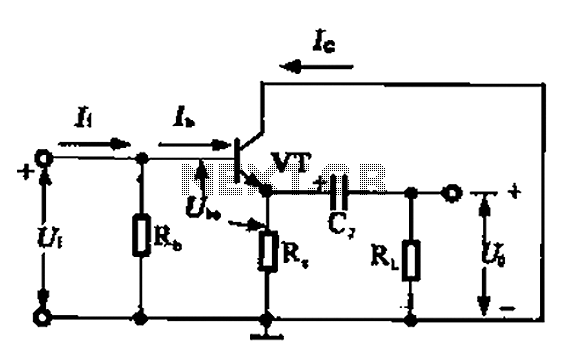
A common collector amplifier circuit can be analyzed through its DC and AC paths. The DC path provides a bias circuit for the power transistor, determining whether it is in an active or off state, primarily influenced by the...
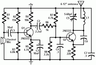
An FM transmitter, commonly referred to as an FM transmitter, utilizes two transistors, specifically the 2N2222 model. When in operation, this FM transmitter requires a 9-volt battery for power and operates with an antenna that is less than 12...
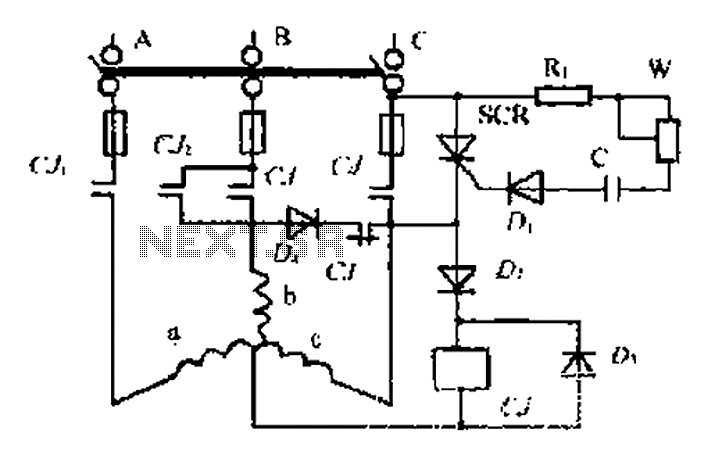
AC contactor controls suction units, with the motor activated simultaneously. A pair of contacts (CJ1) short-circuits the thyristor (SCR), turning it off. The contactor (C) is influenced by the diode's DC voltage. In the positive half-wave power cycle, the...