
Level one thyristor-controlled circuit sink type b
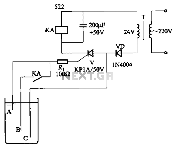
The circuit operates by employing a thyristor, which is a semiconductor device that acts as a switch, allowing current to flow only when triggered by a gate signal. In this application, the thyristor is used to control the flow of current based on the liquid level detected by the electrodes. When the liquid level reaches a certain point, the electrodes become conductive, triggering the thyristor and allowing current to pass through.
The inclusion of a current limiting resistor (Ri) is critical for the protection of the thyristor. This resistor ensures that the gate current does not exceed the maximum ratings specified by the manufacturer, thus preventing thermal runaway and potential failure of the thyristor. The value of Ri must be carefully calculated based on the supply voltage and the required gate current for the thyristor to operate effectively.
In practical applications, this circuit can be utilized in various liquid level control systems, such as water tanks, chemical storage, and other applications where monitoring and controlling liquid levels is essential. The design can be expanded to include additional features, such as alarm systems or automatic pumps, to enhance the functionality of the liquid level control system. Overall, the integration of a thyristor and a current limiting resistor in this circuit provides an efficient and reliable solution for automatic liquid level control. Circuit shown in Figure 11-14. It uses a one-way thyristor, is poured into the liquid level automatic control circuits. Electrodes for detecting sensing element for water or ot her conductive liquid level control. Figure, Ri current limiting resistor to limit the flow of current through the thyristor gate, so as not to burn the tubes.
Related Circuits
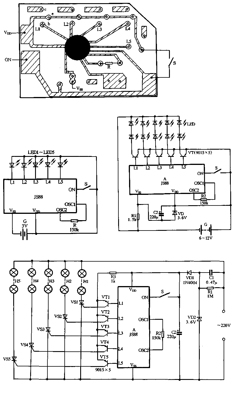
Figure 2-39 illustrates a typical application circuit for the JS88 manifold, which includes an oscillation resistor (R) that allows for fine-tuning of the water flicker frequency. When switch (S) is closed, components L1 to L5 sequentially output low signals...
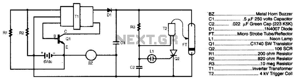
The burglar chaser is an effective accessory for any alarm system. It produces intense flashes of white light and generates a loud, irritating sound using a metal horn buzzer. Transformer T1 is connected to Q1, R1, and R2 to...
This bulletin outlines the applications, design features, equipment arrangement, and space planning for the type 230 controllers. These controllers are designed for the control and protection of induction motors or transformers in 2300-4160 volt systems. Each type 230 controller...
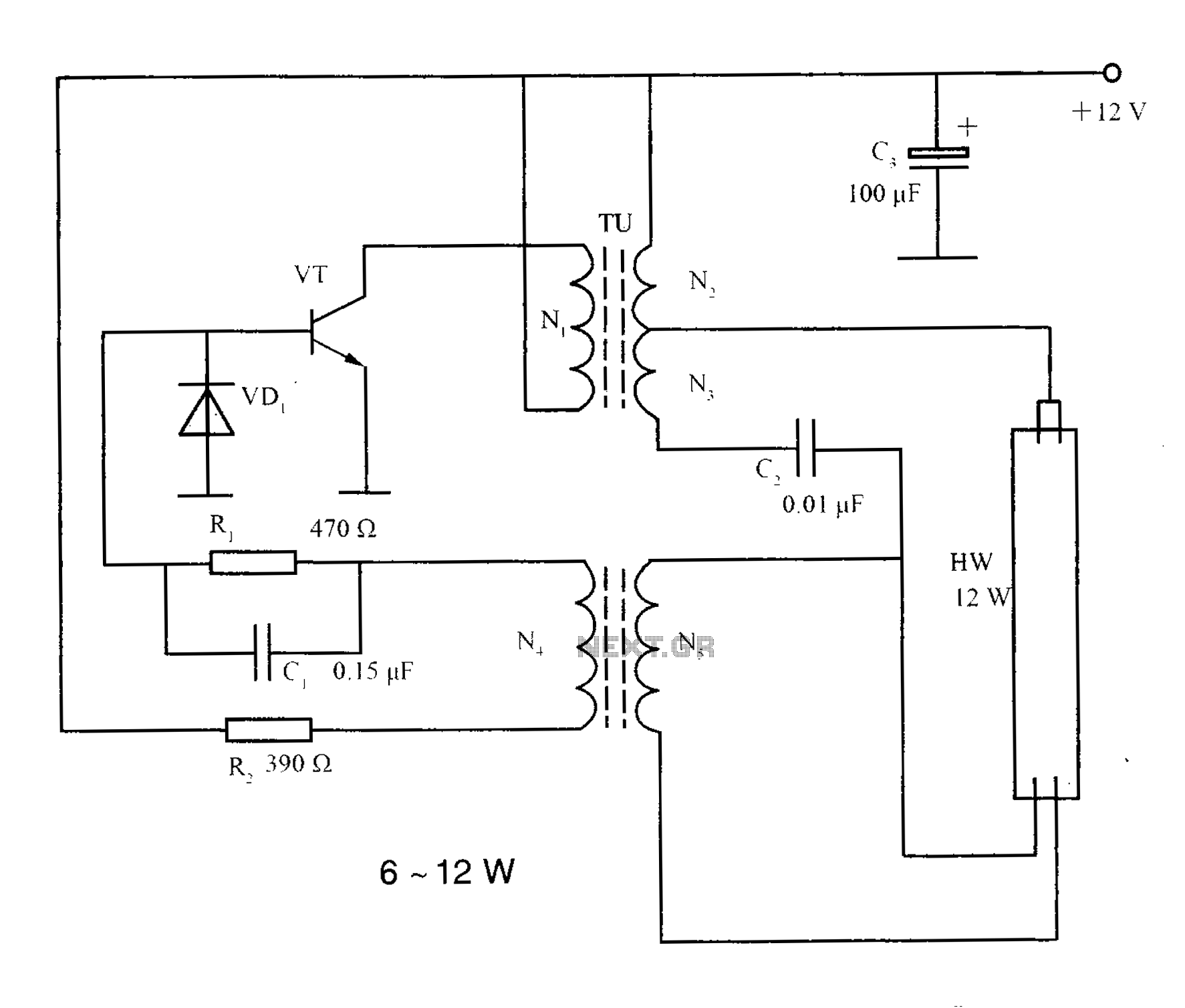
The lighting inverter circuit is designed for 6 to 12W fluorescent lamps. It operates by first bucking the mains voltage, followed by rectification and filtering to charge a battery. When the inverter is activated, it generates a high-frequency alternating...
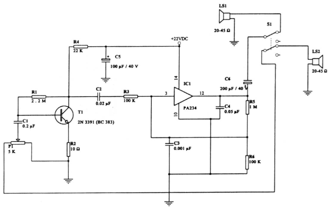
This intercom circuit is versatile and can be utilized in various applications. It operates at 22V, although it may function at a lower voltage (experimental testing is suggested). The circuit utilizes a loudspeaker with an impedance of 20-45 Ohms...
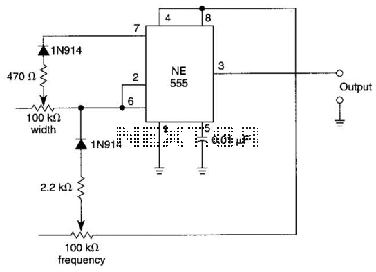
In this multivibrator circuit, frequency and pulse width can be separately controlled by using steering diodes (1N914) and two potentiometers. This multivibrator circuit utilizes steering diodes, specifically the 1N914 type, to enable independent control over both the frequency and pulse...
Warning: include(partials/cookie-banner.php): Failed to open stream: Permission denied in /var/www/html/nextgr/view-circuit.php on line 713
Warning: include(): Failed opening 'partials/cookie-banner.php' for inclusion (include_path='.:/usr/share/php') in /var/www/html/nextgr/view-circuit.php on line 713