
Cheap Motorcycle Alarm

This motorcycle alarm circuit is designed to provide an effective security measure against theft, integrating various electronic components for functionality and reliability. The use of MOSFETs allows for efficient switching, while the relay serves as a crucial component for disconnecting the ignition coil, effectively immobilizing the motorcycle when the alarm is triggered. The circuit's ability to be easily concealed enhances its effectiveness, as potential thieves are less likely to detect its presence.
The connection of the alternator wire through the relay adds a layer of security, ensuring that even if the motorcycle is tampered with, it will not start without the alarm being deactivated. The inclusion of multiple normally-open switches allows for customizable security options, enabling the user to adapt the alarm system to their specific needs.
In addition to the motorcycle alarm functionality, the circuit's design promotes fuel efficiency and reduced emissions, making it an environmentally friendly choice. The integration of a touch alarm circuit further enhances security, providing an additional layer of protection that can be installed discreetly on doors.
Overall, this circuit represents a practical solution for motorcycle owners looking to safeguard their vehicles while also benefiting from improved ignition performance and reduced maintenance costs. The schematic diagram serves as a comprehensive guide for assembling the circuit, ensuring ease of construction and implementation.Cheap motorcycle alarm circuit. During parking, hidden switch S1 is normally open and will not permit triggering of MOSFET T1. But when somebody starts the motorcycle by using ignition switch S2, MOSFET T2 triggers through diode D1 and resistor R5. Relay RL1 (12V, 2C/O) energises to switch on the alarm (designed close to IC1) as well as to disconn ect the ignition coil from the circuit. Disconnection of the ignition coil avoids generation of spark from the spark plug. Generally, you will find there`s wire running from the alternator towards the ignition coil, which needs to be routed through one of the N/C1 contacts of relay RL1 as shown in the circuit diagram. This is simple to build and cheap motorcycle alarm circuit which could be fitted in motorcycles to take care of them from getting stolen.
The tiny circuit may be hidden anyplace, without having any difficult wiring. Practically, it fits all motorcycles as long as they`ve a electric battery. It is not going to drain out. The following circuit is a simple, cheap and easy build motorcycle alarm. The circuit just required 2 transistors to drive the relay the the relay act as a switch to activate the buzzer. Any number of normally-open switches may possibly be applied. Fit the mercury switches to ensure that they close when the steering is. This transistor ignition circuit give your car to have better starting and smoother running, particularly at very high and very low RPM.
Lower fuel consumption, less pollution, lower servicing costs. Drive economically, drive electronically. Only for petrol/gasoline engines. This circuit will reduce breaker point wear and provide cleaner spark. Circuit diagram: Wiring diagram with the. This car headlight alarm circuit can be set for one or two functions: First, to indicate that the head lights (or the side lights) should be switched off after switching off the ignition contact. With this circuit, there should be no dead battery due to headlights that were left on. Second, to indicate that the. The schematic diagram shown right here is the automatic switching-on emergency light circuit which is controlled using IC.
The most important capabilities of this circuit are: automatic switching-on of the light on main power failure and battery charger with overcharge protection. When mains electrical power is absent, relay RL2 is in deenergised state, feeding DC. Touch Alarm circuit is widely used for security, which is installed on the door. The advantages of this alarm is because the cost is cheap and difficult to detect by burglars / intruders.
The following is an example of a touch of alarm circuit which is designed by Tony Van Roon. Components List: R1 =. 🔗 External reference
Related Circuits

Although today's electrical appliances are increasingly self-powered, especially portable ones used for camping or summer holidays, there are still occasions when a 230 V AC source is necessary. If the power requirement from such a source remains relatively low—here,...

This circuit functions as a flood alarm using several bipolar transistors. When liquid comes into contact with the probes, a leakage current biases Q1, Q2, and Q3 (configured as a direct current-coupled amplifier) into conduction, thereby activating the relay....

This is a simple transistor-based burglar alarm circuit. Its features include automatic exit and entry delays, along with a timed bell cut-off and reset. It is designed to be used with common types of normally-closed input devices such as...
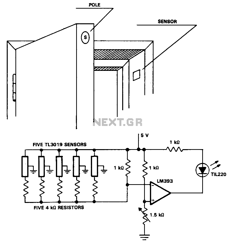
The TL3019 device activates, or goes low, when a south pole of a magnet approaches the chip face. In this example, there are five doors, each equipped with a magnet embedded in its edge, with the south pole facing...
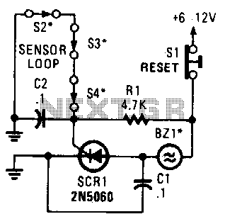
A string of three series-connected, normally closed switches is connected across the gate of a silicon-controlled rectifier (SCR). When one switch opens, the SCR is triggered through resistor R1, activating an alarm. The alarm is designed to be of...

The schematic illustrates a Simple Motorcycle Alarm Circuit Diagram created by Ron J. It incorporates micro-switches to safeguard removable panels and... The Simple Motorcycle Alarm Circuit Diagram is designed to enhance the security of motorcycles by utilizing a series of...