
High speed paper tape reader

The output threshold and tape translucency requirements are met by monitoring the output voltage and enabling operation at 2000 bits per second under ambient light levels equivalent to signal levels.
The described circuit is structured to facilitate the reliable interfacing of peripheral devices through the use of logic signal levels, which are essential for digital communication. The nominal output voltage of 4 V signifies a logic high state, while the drop to -0.6 V indicates a logic low state when the optical sensor is illuminated by the tape. This behavior is crucial for accurately reading data from high-speed paper tape optical readers.
Operating at speeds up to 1000 bits per second allows for efficient data transmission, while the capability to handle tape translucency that transmits 50% of incident light ensures versatility in various lighting conditions. The design emphasizes cost-effectiveness without compromising performance, making it suitable for applications where budget constraints are a consideration.
The implementation of cascode constant voltage biasing serves to enhance the response time of the photodarlington transistor, thereby improving the overall speed and efficiency of the optical reading process. This configuration minimizes the effects of voltage variations and optimizes the sensor's performance, ensuring that it reliably detects the light signals corresponding to the data encoded on the tape.
Moreover, the ability to operate at 2000 bits per second under ambient light levels comparable to signal levels indicates that the circuit is robust against noise and fluctuations in the environment. By continuously monitoring the output voltage, the circuit can dynamically adjust to maintain the required threshold for accurate data interpretation. This adaptability is particularly beneficial in real-world applications where lighting conditions may vary significantly.
In summary, this circuit design not only meets the fundamental requirements for interfacing with computer peripherals but also incorporates advanced techniques to enhance performance, making it a reliable solution for high-speed optical reading applications.When computer peripheral equipment is interfaced, it is convenient to work with logic signal levels. With a nominal 4 V at the output dropping to - 0.6 V on illumination, this circuit reflects the requirements of a high-speed, paper tape optical reader system. The circuit operates at rates of up to 1000 bits per second. It will also operate at tape translucency such that 50% of the incident light is transmitted to the sensor, and provide a fixed threshold signal to the logic circuit, all at low cost.
Several circuit tricks are required. Photodarlington speed is enhanced by cascode constant voltage biasing. The output threshold and tape translucency requirements are provided for by sensing the output voltage and operating to 2000 bits per second at ambient light levels equal to signal levels.
Related Circuits
The simplest of all motor controllers (besides a straight on/off switch) is the contactor controller. Aaron designed this contactor controller for use in his electric scooter project. It is based around three 12V relays, two 12V batteries, two switches...
The 0.1µF monolithic capacitors will be marked '103 K' and the 15pF monolithic capacitors are marked '15 J'. It is crucial not to confuse the two. Do not remove either the MOSFETs or the integrated circuits from their protective...
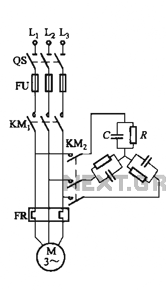
The circuit illustrated in Figure 3-151 consists of capacitor banks arranged in a specific configuration. Figure 3-151 (a) depicts capacitor banks connected in a shaped configuration, which is suitable for shaped or Y-connected motors. Figure 3-151 (b) shows Y-connected...
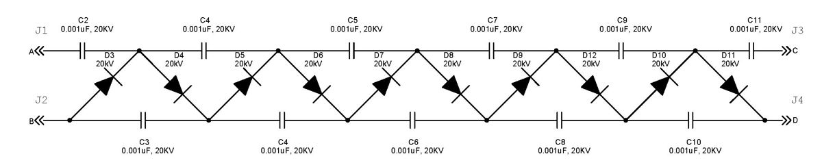
The Cockcroft-Walton multiplier employs a series of diodes and capacitors arranged in a cascade to generate a high-voltage DC potential from an AC input. This circuit topology utilizes diodes to charge capacitors in parallel and discharge them in series....

The purpose of this circuit is to maintain a permanent magnet DC motor at a constant speed, which is set externally. This is achieved by monitoring the current flowing through and the voltage across the motor's brushes. The schematic for...
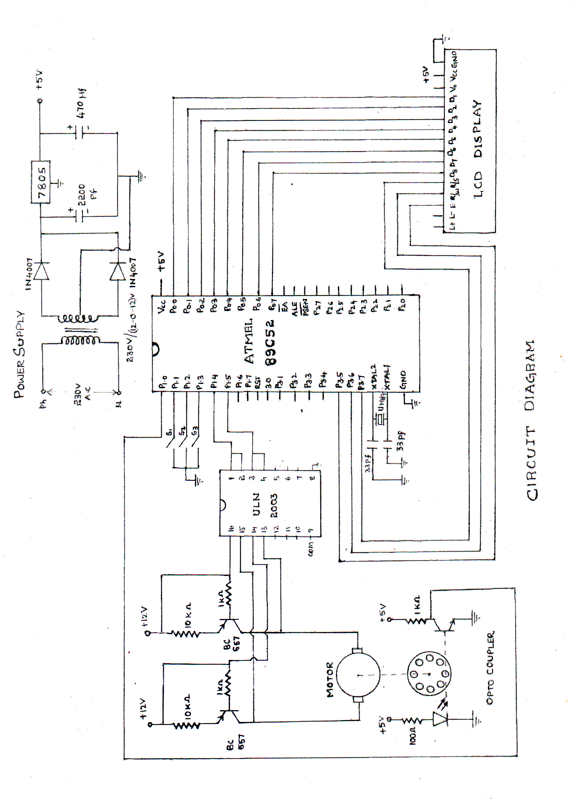
The speed of the DC motor is controlled using an ATMEL89C52 microcontroller, with feedback provided by an optocoupler. The circuit diagram can be viewed above (click on the diagram for a larger view). The motor speed is regulated by...