
DC Motor Speed Controller
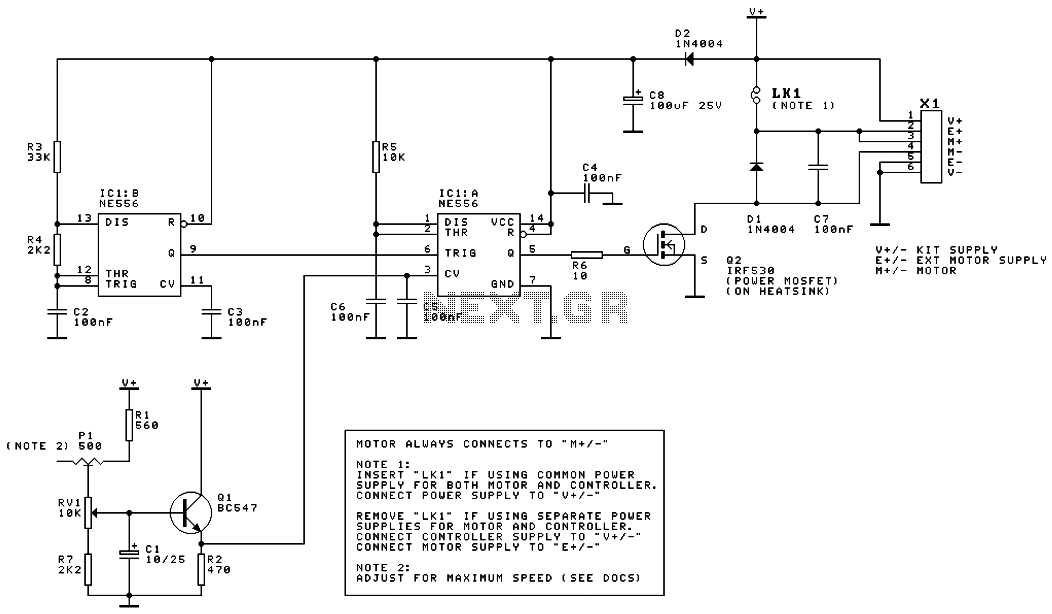
The DC motor speed controller circuit employs a dual timer configuration to generate PWM signals that control the speed of a DC motor. The two oscillators work in tandem, producing a variable duty cycle output that modulates the average voltage supplied to the motor, effectively controlling its speed.
The circuit typically consists of a 555 timer IC or a similar dual timer chip, which is configured in astable mode to generate the PWM signal. The output from the timer is fed into a transistor or MOSFET, which acts as a switch to control the power delivered to the motor. The duty cycle of the PWM signal can be adjusted by varying the resistances and capacitance in the timer circuit, allowing for fine control over the motor speed.
In addition to the timer and switching components, the circuit may also include additional elements such as diodes for flyback protection, capacitors for filtering, and resistors for setting the timing parameters. The inclusion of these components ensures stable operation and protects against voltage spikes that can occur when the motor is turned off.
Overall, this DC motor speed controller circuit is an efficient solution for applications requiring variable speed control, such as in robotics, conveyor systems, and various automated machinery. The use of PWM not only enhances the control over the motor speed but also improves energy efficiency compared to other control methods.This is the schematic diagram of DC motor speed controller circuit. The circuit applies two oscillators/timers which are connected as a Pulse Width Modulator (PWM). The timer chip which applied in this circuit will be an nmos dual timer/osc.. 🔗 External reference
Related Circuits
PWM is a device that can be utilized as an efficient light dimmer or DC motor speed controller. Function: for a general-purpose device that can... PWM (Pulse Width Modulation) is a versatile technique widely employed in various electronic applications, particularly...
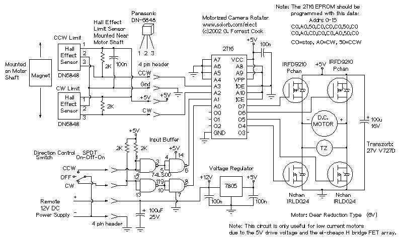
The camera rotator circuit uses a 2716 EPROM to store a table of logic values that control the motor driver (H-bridge) circuit. The EPROM data is shown in the schematic. By using the EPROM, a large number of discrete...
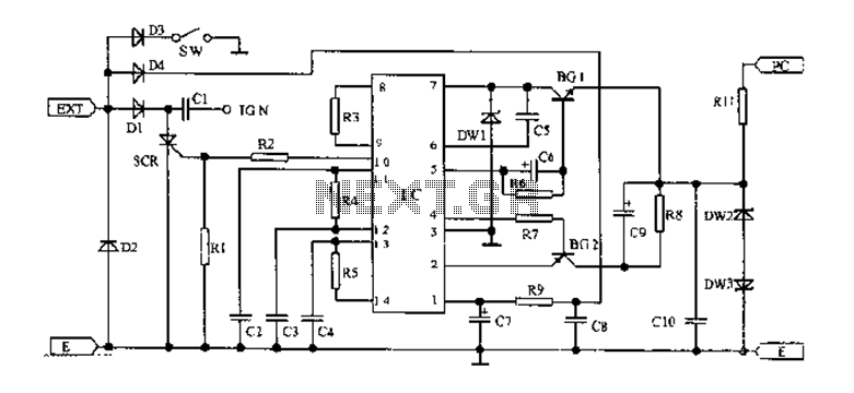
An AC magneto is connected to an external circuit. The output is rectified by diode D1 and stored in capacitor C1. Additional rectification is performed by diodes D4, along with resistors R9 and capacitors C7 and C8, which filter...
The SS0001 human pyroelectric voice alarm circuit diagram is designed for use as a pyroelectric infrared warning device, which can help prevent electric shock or theft. With minor modifications, it can also function as an automatic light switch. This...
For beginners in microcontroller projects who are unsure where to start, this project serves as one of the simplest options available. It provides a clear understanding of programming a microcontroller. Often, one may glance at a watch and ponder,...
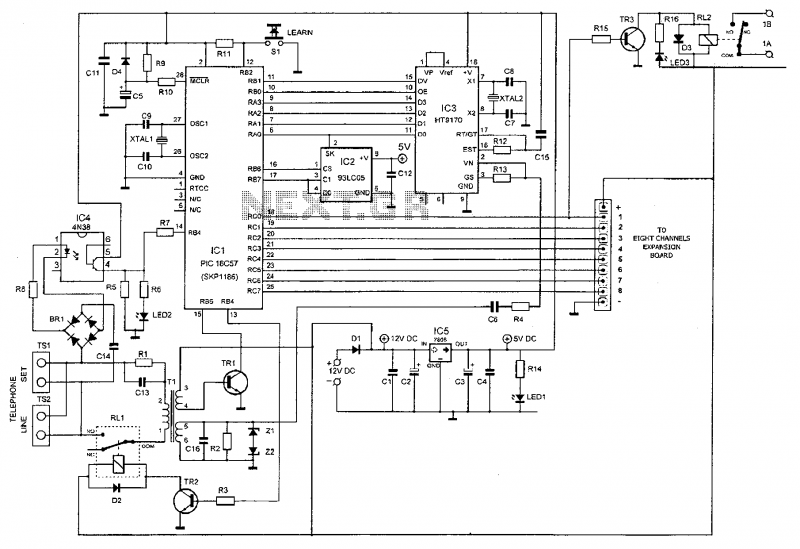
This device enables remote control of various appliances (up to eight with suitable add-on expansion boards) such as lights, water heaters, air conditioning, plant watering systems, alarms, etc., via a relay. It allows users to perform actions such as...