
Motorized Camera rotator
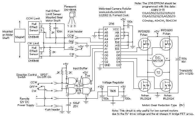
The camera rotator circuit is designed to provide precise control over the rotational movement of a camera using a motor driver configuration. At the heart of the circuit is a 2716 EPROM, which serves as a programmable read-only memory device. This EPROM contains a logic table that dictates the operational states of the motor driver, specifically an H-bridge configuration that allows for bidirectional motor control.
The circuit operates by receiving inputs from limit sensors that detect the position of the motor. These sensors are crucial for preventing mechanical overrun and ensuring that the motor stops when it reaches its designated limits. The logic table stored in the EPROM is programmed to enable the motor to rotate in a clockwise direction until the clockwise limit sensor is triggered. A similar arrangement is in place for counterclockwise rotation, where the motor will continue to operate until the counterclockwise limit sensor is activated.
Control signals for the motor's direction are provided through two control switches, which allow the user to dictate the desired rotation. These control signals are then buffered using a 7400 quad NAND gate, a component that enhances signal integrity and allows for longer cable runs without degradation of the control signals. This buffering is particularly important in applications where the control switches may be located at a distance from the motor driver circuit.
The outputs from the EPROM are directed to the gates of four transistors in the H-bridge configuration, which are responsible for driving the motor. This arrangement allows for efficient control of the motor's direction and speed, while the use of the EPROM significantly reduces the number of discrete logic gates that would otherwise be required in a more traditional design.
Overall, the camera rotator circuit exemplifies an efficient approach to motor control, leveraging programmable logic to simplify the design and enhance functionality.The camera rotator circuit uses a 2716 EPROM to store a table of logic values that control the motor driver (H-bridge) circuit. The EPROM data is shown in the schematic. By using the EPROM, a large number of discrete gates are eliminated. The logic table is designed to allow the motor to turn clockwise until the clockwise limit sensor is activated.
The same operation happens with counter clockwise rotation and the counter clockwise limit sensor. Inputs to the EPROM come from the limit sensors and the two control switch directions. Outputs go to the four H-bridge transistor gates. The control switch signals are buffered through the 7400 quad NAND gate, this allows for a long control wire. All of t 🔗 External reference
Related Circuits
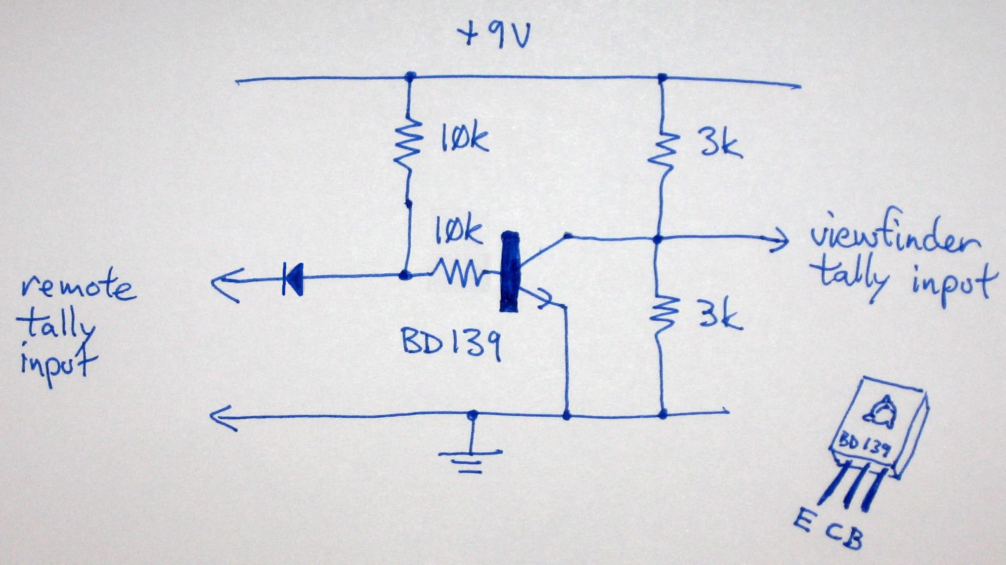
Instructions for enabling the tally light on the F15 camera viewfinder without access to the CCU/RCU. To activate the tally light on an F15 camera viewfinder in the absence of a Camera Control Unit (CCU) or Remote Control Unit (RCU),...
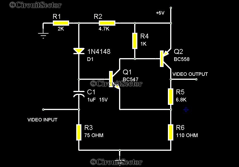
There are instances when it is necessary to view video clips captured by a digital camera on a television. This can be accomplished by connecting the camera's video output to the television's video input. However, a direct connection is...
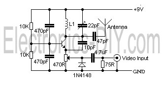
This is a simple video transmitter capable of transmitting signals up to 50 meters. It can be connected to a camera or other video sources, allowing viewing on a VHF channel analog TV. The transmitter operates on a supply...
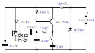
If you wish to take a picture of a fleeting event which generates a sound, you can do it with this sound activated trigger. It does not require any power supply: it feeds on the high voltage available on...
The circuit diagram for a multiple output digital camera power supply using the MAX1802 is illustrated below. The MAX1802 chip features two buck converters and three boost converters. It accepts an input voltage range of 2.5 to 11V and...
I built this cable for my Casio QV-200 digital camera, it should work for many Casio models. It's basically an inverting buffer/converter to/from RS-232 voltage levels from/to CMOS levels. Why Casio didn't put this inside the camera like everyone...