
Troubleshooting a Triac Motor Control Circuit
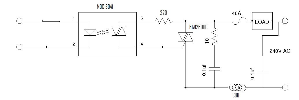
The circuit under discussion involves a triac-based control system designed for an AC motor, specifically a solder vacuum pump. The MOC 3041 optoisolator serves as a zero-crossing detector, which is crucial for reducing electromagnetic interference and ensuring smooth operation of the motor. The BTA12 600C triac is responsible for switching the AC load, allowing current to flow to the motor when activated.
The presence of two 1 µF capacitors in the circuit serves a dual purpose: they act as snubber capacitors to protect the triac from voltage spikes during switching and also help to filter noise that may affect the performance of the motor. The resistors present in the circuit help to limit current and ensure that the triac operates within its specified limits.
The issue with the current surge upon releasing the button could be attributed to several factors. One possibility is that the motor's inductive load is causing back EMF (electromotive force) when the current is interrupted, leading to a sudden spike in voltage that the circuit is not designed to handle. This phenomenon can cause the triac to latch or malfunction, resulting in a blown fuse.
To troubleshoot the problem further, it is advisable to examine the circuit layout for any potential short circuits or poor solder joints that may contribute to erratic behavior. Additionally, testing the triac's gate sensitivity and ensuring that it is not overly sensitive to transients could help mitigate the surge issue. It may also be beneficial to incorporate a flyback diode across the motor terminals to safely dissipate any back EMF generated when the motor is turned off, thereby protecting the triac and associated components from damage.Even thought the power was off there was AC at the handle plug and I shorted something. I pulled it apart and found a transistor blown apart. I figured it would be an easy fix. One month, twenty plus dollars in parts and many changes of components it is still not working correctly. The problem is on the right side, the handle with the solder vacuum pump. When you press the button on the handle the pump turns on and runs and when you let the button go, the pump will run for a few seconds, like it should and then there will be a big surge in current and sometimes it will blow the fuse on the Xytronic. This big surge shouldn`t be there. Everything else is working as it should. I looked into this circuit and it is using a zero crossing triac in a six pin DIP. A MOC 3041 this triggers the triac a BTA12 600C. It has a coil, two. 1uf caps or protection devices. A few resistors in this part of the circuit. I check them all out of circuit and they seem to check OK. It is kind of typical of AC triac motor circuit. I tried to upload the schematic but I am having problems with the cookies on this site and it won`t let me do it because it things this is my first question.
What looks simple, and just might be has me perplexed. What would cause this big surge of current when the motor stops Thank you, Russ This is the schematic from the motor part of the circuit board. The load goes to a small AC motor 110V. It isn`t 240V, as marked in the picture. it is all 110. I took a schematic I found on the web and changed a few parts in paint shop to get it match what I had.
It seems like I see this type of circuit in a number of places. The. 1uF are square plastic film or some kind of protection caps. Thanks again, Russ 🔗 External reference
Related Circuits

The TS-440S, similar to several other radios, does not mute the microphone when utilizing the rear audio connector for digital modes. Consequently, unless the microphone is unplugged each time digital modes are used, background noise from the shack can...

The travel remote control model is represented by a circuit diagram. The NE556 is a dual time base IC that includes two separate circuits, each consisting of a Schmitt trigger circuit. The output control is achieved through the TX315B1,...

The LM12 audio amplifier circuit is designed to deliver high output power for 8 ohm or 4 ohm load impedances. The maximum output power provided by the LM12 audio amplifier is approximately 60 watts for a 4 ohm load...
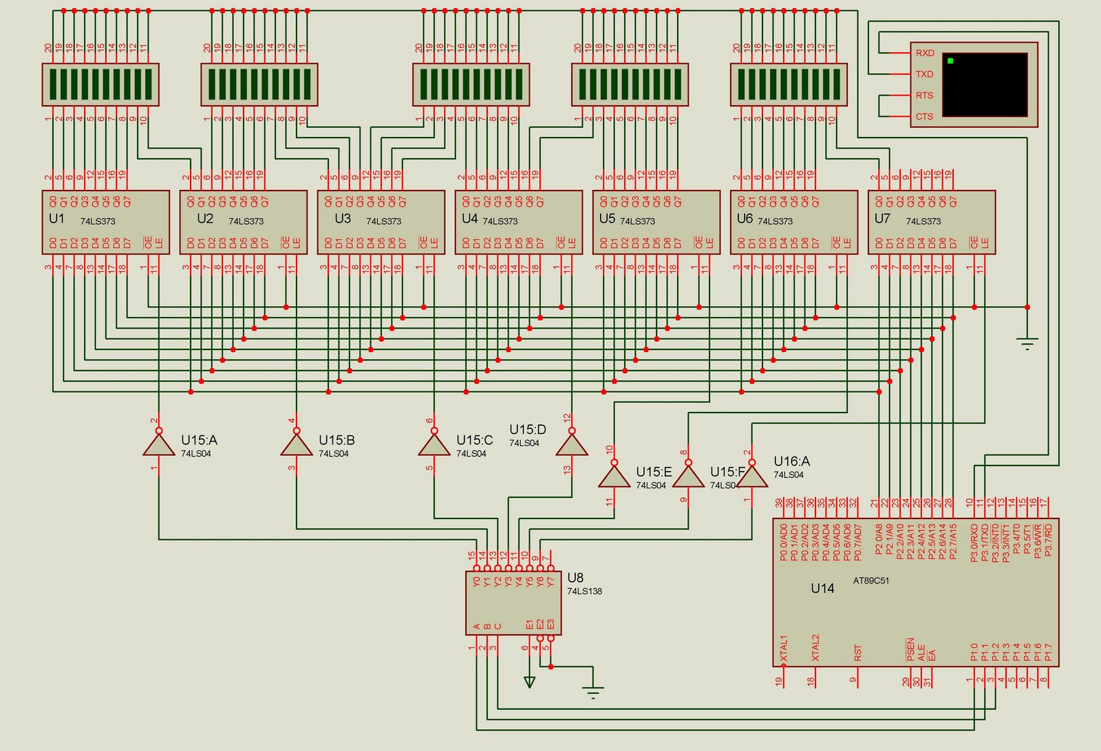
This project is designed to control up to 50 solid-state relays independently. It serves as an excellent learning resource for students who wish to expand the input-output lines of a microcontroller and control multiple devices. The ON or OFF...
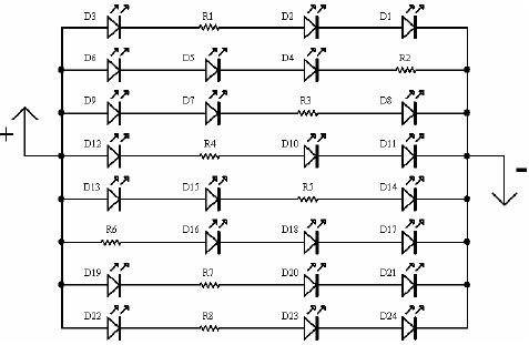
A light-emitting diode (LED) lamp is a solid-state lighting device that utilizes light-emitting diodes as its light source. LEDs are a cost-effective and convenient choice for various lighting applications. They are available in an extensive range of colors, styles,...
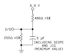
A device that conducts electric current and converts electrical energy into another form. Power consumed by a device or circuit while performing its function can be represented by a resistor and capacitor. The capacitor in the load circuit represents...
Warning: include(partials/cookie-banner.php): Failed to open stream: Permission denied in /var/www/html/nextgr/view-circuit.php on line 713
Warning: include(): Failed opening 'partials/cookie-banner.php' for inclusion (include_path='.:/usr/share/php') in /var/www/html/nextgr/view-circuit.php on line 713