
Motor Turn Stall Detector
In single-phase AC induction motors, the operation of the start winding is essential for initiating rotation. The start winding is designed to create a phase shift that allows the motor to overcome inertia and begin turning. The capacitor used in series with the start winding is crucial for establishing this phase difference, which typically ranges from 5 to 20 microfarads, depending on the motor's design specifications.
The triac employed in place of the centrifugal switch serves to electronically control the start winding, allowing for more precise activation and deactivation based on the motor's operational state. The triac is triggered by a control circuit that monitors the motor's speed, ensuring that the start winding is only engaged during the initial start-up phase and is turned off once the motor reaches a predetermined speed.
The detection of motor rotation is accomplished by sensing the induced voltage in the start winding. This voltage can be monitored using a microcontroller or a simple comparator circuit, which compares the phase of the induced voltage with the mains voltage. When the motor is running, the phase difference will indicate that the start winding can be safely deactivated. Conversely, when the motor stops, the phase alignment of the induced voltage with the mains voltage signals that the start winding may need to be re-engaged to restart the motor.
Protection mechanisms such as current sensing resistors or thermal overload switches can be integrated into the circuit to prevent overheating and potential damage to the motor. These components can be used to cut off power to the motor in the event of a stall condition, ensuring safe operation and longevity of the motor.
Overall, careful consideration of the circuit design, including the integration of the triac, capacitor, and protective measures, is essential for the reliable operation of single-phase AC induction motors in household appliances. Proper schematic representation and adherence to electrical safety standards are crucial for successful implementation.In single phase AC induction motors, often used in fridges and washing machines, a start winding is used during the starting phase. When the motor has reached a certain speed, this winding is turned off again. The start winding is slightly out of phase to the run winding. The motor will only start turning when the current through this winding is o ut of phase to that of the run winding. The phase difference is normally provided by placing a capacitor of several µF in series with the start winding. When the motor reaches a minimum speed, a centrifugal switch turns off the start winding. The circuit diagram doesn`t show a centrifugal switch; instead it has a triac that is turned on during the staring phase.
For clarity, the series capacitor isn`t shown in the diagram. Once the motor turns it will continue to do so as long as it isn`t loaded too much. When it has to drive too heavy a load it will almost certainly stall. A large current starts to flow (as the motor no longer generates a back EMF), which is limited only by the resistance of the winding. This causes the motor to overheat after a certain time and causes permanent damage. It is therefore important to find a way to detect when the motor turns, which happens to be surprisingly easy.
When the motor is turning and the start winding is not used, the rotation induces a voltage in this winding. This voltage will be out of phase since the winding is in a different position to the run winding. When the motor stops turning this voltage is no longer affected and will be in phase with the mains voltage.
The graph shows some of the relevant waveforms. More information can be found in the application note for the AN2149 made by Motorola, which can be downloaded from their website at We think this contains some useful ideas, but keep in mind that the circuit shown is only partially completed. As it stands, it certainly can`t be put straight to use. We should also draw your attention to the fact that mains voltages can be lethal, so take great care when the mains is connected!
🔗 External reference
Related Circuits
This page shows some methods of track routing control for Stall-Motor type switch machines. The principle method uses a 2 Pole - Multi Position rotary switch while an alternate uses optoisolators and transistors to select the routes. The last...
%2Busing%2Bop%2Bamp%2B741%2Bic%2B.png)
A zero crossing detector (ZCD) is a voltage comparator that switches its output between +Vsat and -Vsat (where Vsat is the saturation voltage, approximately 14V) when the input crosses the zero reference voltage. Comparators are fundamental operational amplifier circuits...
This circuit generates the power required to operate a bipolar stepper motor. It allows for adjustments in both the rotation speed and direction of the motor. The design includes two integrator circuits (A1, A3) and an amplifier (A2) connected...
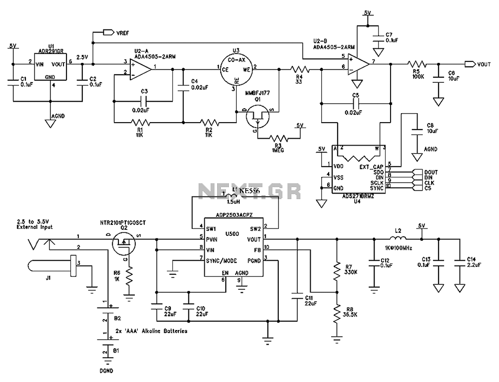
The circuit diagram presented below illustrates a portable gas detector. This device primarily utilizes electrochemical sensors and features dual-channel micro-power amplifiers, specifically the ADA4505-2. These amplifiers are configured in both a constant potential (U2-A) and a transconductance configuration (U2-B)....
This integrated circuit is highly efficient and does not require any external glue logic for operation. It features two pins to control a motor: one for direction and the other for stepping pulse triggers. The design is compact and...
The circuit is straightforward and cost-effective. This is advantageous since most commercially available stepper motor controller ICs tend to be quite pricey. It is constructed using standard components and can be easily modified for computer control. By utilizing inexpensive...