
DC Motors and Stepper Motors used as Actuators
DC motors, electrical motors, and stepper motors are integral components in various applications, functioning as actuators to convert electrical energy into mechanical motion. Each type of motor operates on distinct principles and is suited for different tasks.
DC motors are characterized by their simplicity and efficiency in converting direct current electrical energy into rotational motion. They typically consist of a rotor, stator, commutator, and brushes. The rotor, or armature, is the rotating part of the motor, while the stator provides a magnetic field. The direction and speed of the motor can be controlled by varying the voltage supplied to it. Pulse Width Modulation (PWM) is a common technique used to efficiently control the speed of DC motors by adjusting the average voltage delivered to the motor, thereby managing its power consumption and performance.
Electrical motors encompass a broader category that includes AC motors, which differ from DC motors in that they operate on alternating current. These motors can be further classified into synchronous and asynchronous types, each with unique characteristics suitable for specific applications. Synchronous motors maintain a constant speed regardless of the load, while asynchronous motors, or induction motors, vary their speed based on the load conditions.
Stepper motors are a specific type of electric motor that move in discrete steps, allowing for precise control of position and speed. They are widely used in applications requiring accurate positioning, such as 3D printers, CNC machines, and robotics. The control of stepper motors is typically achieved through a sequence of electrical pulses, which energize the motor coils in a specific order to produce movement.
Transistor H-bridge motor control is a technique utilized to control the direction and speed of DC motors and stepper motors. An H-bridge circuit consists of four switches (transistors) arranged in an "H" configuration, allowing current to flow through the motor in either direction. By turning on different combinations of the transistors, the H-bridge can reverse the motor's direction or stop it entirely. This method provides a flexible and efficient means of motor control, enabling complex motion patterns and precise speed regulation.
In summary, understanding the principles and control methods of DC motors, electrical motors, and stepper motors is crucial for designing effective actuator systems in various electronic applications. The integration of PWM and transistor H-bridge control enhances the functionality and efficiency of these motors, making them essential components in modern electronic devices.Electronics Tutorial about DC Motors, Electrical Motors and Stepper Motors used as Actuators including PWM and Transistor H-bridge Motor Control.. 🔗 External reference
Related Circuits
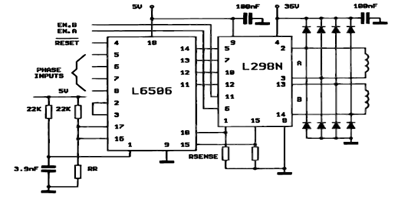
The following figure illustrates the control circuit for a two-phase bipolar stepper motor utilizing the current controller L6506. The L6506 integrated circuit generates the necessary signals to drive the inputs of the L298 bipolar stepper motor circuit driver. The circuit...
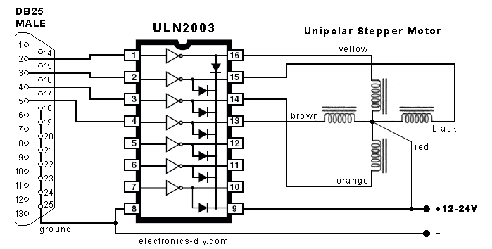
In the search for stepper drivers, the ULN2003 chip was discovered, which facilitates motor operation with minimal circuitry through the parallel port of a PC. However, the current output from the ULN2003 is limited to 500mA, resulting in low...

If the control circuit of this motor driver is based on a microcontroller or digital component, it is advisable to implement a buffer for each port that controls the stepper motor driver. This precaution helps prevent overloading the microcontroller...
Stepper motors come in various versions and sizes, accommodating a range of operating voltages. This general-purpose controller is capable of functioning with voltages from approximately 5 V to 18 V, driving the motor with a peak voltage equal to...
Select a free schematic drawing software that resembles the two mentioned. There have been discussions regarding circuit drawing software. Fritzing is favored, although it lacks certain components, such as the RS232 component. There is a request for feedback on...

The prototype circuit board utilized an external LCD display that received commands through an RS-232 interface. While this setup functioned adequately, programming it was cumbersome. Consequently, the circuit board was revised to support a directly attached LCD display. The...