
Current amplification for driving stepper motor
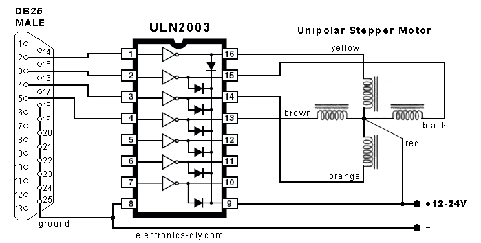
The ULN2003 is a popular Darlington transistor array used for driving inductive loads such as stepper motors. Its limitation of 500mA output per channel can lead to insufficient torque for applications requiring higher performance. When considering alternatives like the LMD18200, which can handle up to 3A, it is crucial to evaluate the motor's specifications and the system's overall design to ensure compatibility and efficiency.
The use of a parallel port for controlling the stepper motor phases introduces a bottleneck in speed, particularly when managing multiple axes. This approach may not be suitable for applications demanding rapid and precise movements. Transitioning to a dedicated stepper driver IC, such as the A4988 or DRV8825, would provide improved control and current handling capabilities, allowing for smoother and more responsive motor operation.
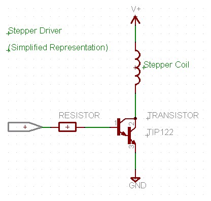
For a more robust design, incorporating MOSFETs as switches can enhance performance. In this case, a dedicated driver IC can effectively drive the MOSFETs, eliminating the need for additional buffer stages. Furthermore, implementing full-stepping control through logic ICs provides a reliable means of driving the stepper motor without the complexities associated with using multiple ULN2003 chips in parallel.
In terms of power supply considerations, connecting multiple ULN2003 chips in parallel does not increase the current output beyond the power adapter's limit. Therefore, if the power adapter is rated for only 500mA, achieving a total of 1.5A is not feasible without upgrading the power supply. Additional components, such as ceramic power resistors and large capacitors, may be required to stabilize the circuit and improve performance, particularly when using MOSFETs. Overall, a comprehensive redesign focusing on a dedicated driver solution, appropriate power supply, and optimized control logic will yield significantly better results for driving stepper motors in multi-axis applications.Looking for Stepper drivers i came across ULN2003 chip which allowed me to run the motor with minimum circuitry through the parallel port on my PC( I`m not an electronics person, hence searched for the simplest option out there). But the problem is the current output from ULN2003 is only 500mA. and hence the torque from the motor is very low ( i can stop it very easily using my hand) (if its of any help i came across this chip LMD18200 with current output of 3A. if its possible to drive the motor with any such chip that wud be wonderful) your design uses the parallel port to control each phase of the stepper. this is bound to be very slow! with 3 axis doing this, you are probably going to have trouble. if you want to use mosfets, you do not need the buffer chip. a better choice would be to look for a dedicated stepper driver chip to power the mosfets, or darlington transistors, as they may prove more practical.
unless your budget is very small, i would recommend looking at a better drive system. even a discrete driver using logic ICs to do `full stepping` will be significantly better than your current intentions. i used what you have on a 2D plotter device, and it sorta worked. You need o add in some more components to make just mosfets work relialably. i believe you will also need 1, 2, or more ceramic `power resistors`, a large capacitor. etc. your design uses the parallel port to control each phase of the stepper. this is bound to be very slow! with 3 axis doing this, you are probably going to have trouble. if you want to use mosfets, you do not need the buffer chip. a better choice would be to look for a dedicated stepper driver chip to power the mosfets, or darlington transistors, as they may prove more practical.
unless your budget is very small, i would recommend looking at a better drive system. even a discrete driver using logic ICs to do `full stepping` will be significantly better than your current intentions. i used what you have on a 2D plotter device, and it sorta worked. You need o add in some more components to make just mosfets work relialably. i believe you will also need 1, 2, or more ceramic `power resistors`, a large capacitor. etc. Abt th design. frankly i chose this one just because im a rookie in the field of electronics and at that time all i inetended to do was to check whether my motor was working or not.
So, in my desperation to get things moving i bought a few more ULN2003s since i had a faint recollection abt somebody telling me to connect these in parallel to get the required current. I know this isnt the best option but if this doesnt work out for me. but yes i had this question in my mind. if im using an adaptor with a current limit of 500mA to power the circuit is it possible to get 1. 5A current even after connecting 4 ULNs in parallel. 🔗 External reference
Related Circuits
The program utilizes two pulse width variables, pw1 and pw2, along with two sets of routines—left1 and left2, and right1 and right2—designated for each motor. The schematic illustrates that the first servo is connected according to the previous circuit...
The objective is to operate a motor using an L293D Motor Drive Shield, which can handle 600mA per coil. The motor consumes 400mA per coil, suggesting compatibility. However, the datasheet does not clearly indicate the pinouts, only labeling them...
The motor control circuit depicted in the image utilizes the LM339 comparator among other components. When the input control signal is high (PWL), comparators A and A3 activate the power amplifier circuit, which consists of A4, VT5, and VT6,...
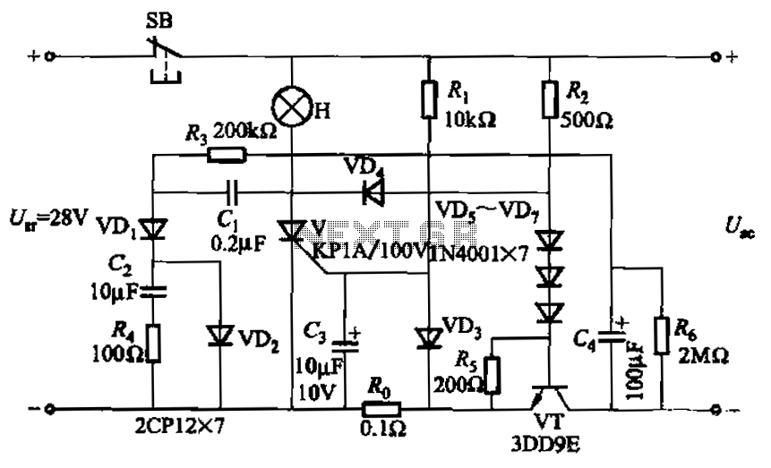
Capacitor C3 is used to determine the cutoff power, specifically the voltage threshold (VT cutoff), which influences the delay time selection. The schematic includes a reset button, SB, that is utilized to reset the system after a failure has...
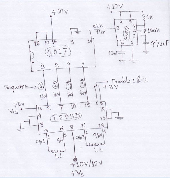
A stepper motor is to be rotated using a Johnson counter 4017 integrated circuit (IC). A bipolar stepper motor is utilized, with connections made from pins 3, 2, 4, and 7 of the 4017 IC following a specific sequence. The...
This program initializes all sixteen I/O lines of the U4x1 to function as outputs. The lower four port pins of port A (A0 - A3) correspond to "channel 1" for stepper motor activity, while the upper four port pins...