
DC Power Supply (5V 10A)
The proposed circuit will employ a 7805 voltage regulator to provide a stable 5V output, necessary for controlling the base of the 2N2955 transistors. This regulator is capable of handling input voltages up to 35V, making it suitable for various power supply configurations. The output from the 7805 will be connected to the bases of the two 2N2955 transistors, which will be configured in parallel to enhance the overall current handling capability of the circuit.
Each 2N2955 transistor can handle a maximum collector current of 15A, but when paralleled, it is essential to ensure that the current is evenly distributed between the two devices. This can be achieved by including small value resistors (typically in the range of 0.1 to 1 ohm) at the emitter of each transistor. These resistors help to balance the load and prevent one transistor from taking on more current than the other, which could lead to thermal runaway.
The collector of each 2N2955 will be connected to the positive terminal of the DC motor, while the emitters will be tied together and connected to ground. The motor itself will be connected between the collector of the transistors and the positive supply voltage. A flyback diode should also be included across the motor terminals to protect the circuit from voltage spikes generated when the motor is turned off.
To control the speed of the DC motor, a PWM (Pulse Width Modulation) signal can be applied to the bases of the transistors through the 7805 regulator. This can be accomplished using a microcontroller or a dedicated PWM generator circuit. The duty cycle of the PWM signal will determine the effective voltage and current supplied to the motor, allowing for smooth speed control.
In summary, the circuit design integrates a 7805 voltage regulator, two parallel 2N2955 transistors, and necessary protective components to create a robust and efficient control system for a DC motor. Proper attention to component specifications and circuit layout will ensure reliable operation and longevity of the system.Hello, I`m planning to design a circuit for a DC Motor with these parts: 1* 7805 2 * 2N2955 (paralleling two transistors to increase current) plus.. 🔗 External reference
Related Circuits
This is a power audio amplifier circuit based on the STK400xx series. It provides high-quality sound and is cost-effective, as the STK40xx series is affordably priced. The circuit can be easily constructed using only a few external components. The...
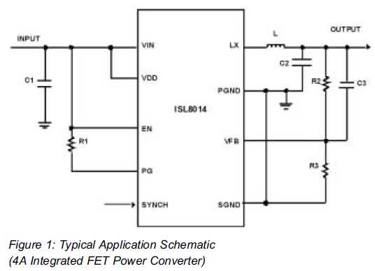
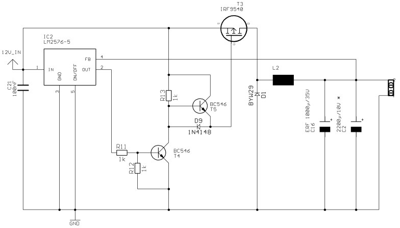
Utilizing Integrated Switching Regulators in Power Supply Design Engineers often find themselves pondering where to begin when designing power supplies. Key decisions must be made regarding... Integrated switching regulators are critical components in modern power supply design, offering efficient voltage...
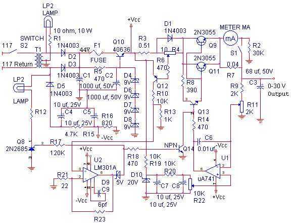
The linear power supply, shown in the schematic, provides 0-30 volts, at 1 amp, maximum, using a discrete transistor regulator with op-amp feedback to control the output voltage. The supply was constructed in 1975 and has a constant current...
Since I have provided the schematic for John L Linsley-Hood's Class-A amplifier, I felt that some readers may wish to experiment with the concept. Unfortunately, a very low ripple power supply is needed for all Class-A amps, and the...
The circuit depicted in FIG. 1 generates a high-voltage signal for controlling the capacitance of barium strontium titanate (BST) capacitors. By applying voltages of V and 3V to the appropriate terminals, the capacitance of the BST can be modified....
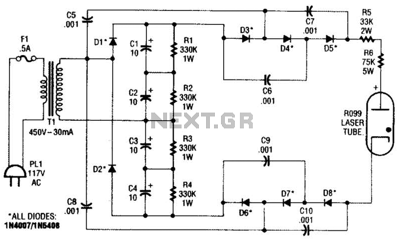
This supply generates an initial high voltage for ignition purposes. After ignition, the supply generates about 1300 to 1500 V. If a higher ignition voltage (than the 6000 V supplied) is necessary, more multiplier stages can be added to...