
DC RMS And Peak-to-Peak High Impedance Voltmeter
The integration of an active buffer circuit into an analog meter serves to improve its input impedance, which is crucial for accurate measurement in various electronic applications. A buffer circuit, often implemented using operational amplifiers (op-amps), isolates the meter from the circuit being tested. This isolation minimizes the loading effect that the meter might impose on the circuit, thereby preventing distortion of the measured signal.
In practical terms, an operational amplifier configured as a voltage follower can be used as an active buffer. The non-inverting input of the op-amp is connected to the signal source, while the output is connected to the analog meter. This configuration allows the op-amp to provide a high input impedance, typically in the range of megaohms, while maintaining a low output impedance. Consequently, the analog meter can accurately reflect the voltage of the source without drawing significant current from it.
The benefits of this approach are particularly evident in high-impedance applications, such as measuring signals from sensors or other sensitive devices. The active buffer circuit ensures that the analog meter can operate effectively without influencing the source signal, thus providing more reliable and precise readings. Additionally, the use of active buffering can enhance the frequency response of the measurement system, allowing for the detection of rapid signal changes that might otherwise be missed with a traditional analog meter.
In conclusion, incorporating an active buffer circuit into an analog meter design not only enhances its input impedance but also significantly improves measurement accuracy and reliability across a range of electronic applications.Analog meter normally doesn`t have high impedance since they don`t have buffer circuit inside. With active buffering, the input impedance of this circuit.. 🔗 External reference
Related Circuits
This circuit utilizes the versatile MAX038 function generator. While some advanced features of this IC are disabled in this configuration, it is capable of generating sine, triangle, and square waves by adjusting the A0 and A1 pins (refer to...
The second-order multipurpose filter described here can function as a low-pass, bandpass, high-pass, or notch filter at audio frequencies. Its unique feature is the ability to independently vary all characteristics using potentiometers. In basic filters, only one k value...
The loads consist of two or more solenoids connected in parallel, sharing a 12V supply. Each solenoid is individually switched to ground through the vehicle's ECU. The objective is to detect when any one of the circuits closes, ensuring...
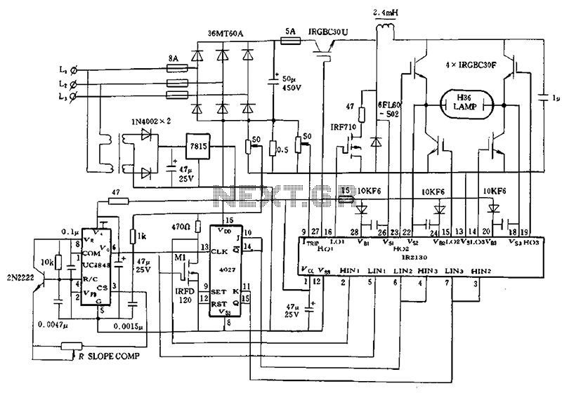
Application of a kilowatt high-pressure mercury lamp ballast system; the schematic in Figure 12.44 illustrates the IR213D used for a high-pressure mercury lamp ballast system. The IR2130 is utilized not only to drive a single-phase full-bridge inverter with four...
This application note provides a concise overview of power amplifier theory and presents simulation results that offer insights into the operation of the power amplifier across all of MAXIM's LFRF transmitters and transceivers. Power amplifiers are critical components in communication...
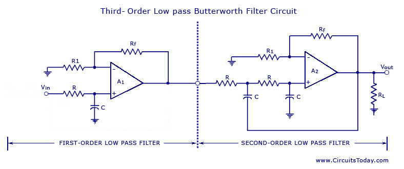
From the discussion made so far on the filters, it can be concluded that in the stopband, the gain of the filter changes at the rate of 20 dB/decade for first-order filters and 40 dB/decade for second-order filters. This...