
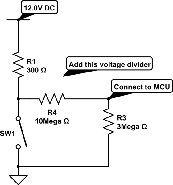
Is there a simpler solution for highside current sensing here
To implement the circuit for detecting solenoid activation, a simple approach using a resistor and a transistor can be utilized. The circuit design involves connecting the solenoids in parallel to a common 12V supply, with each solenoid's ground connection routed through a normally open switch controlled by the ECU.
For detection, a resistor can be placed in series with the solenoid, connected to the ground. The voltage across this resistor will indicate whether the solenoid is activated. When the solenoid is energized, current flows through the resistor, creating a voltage drop that can be monitored. This voltage can be fed into a PIC microcontroller's digital input pin.
To ensure that only one solenoid operates at a time, the ECU should be programmed to sequentially activate each solenoid, allowing sufficient time for the PIC to read the voltage level and determine if the corresponding solenoid is active. The microcontroller can be configured with a simple threshold detection algorithm to ascertain if the voltage exceeds a predefined level, indicating solenoid activation.
If a comparator is preferred for detection, it can be configured to compare the voltage across the resistor with a reference voltage. When the solenoid is activated, the voltage will exceed the reference level, triggering the comparator output, which can then be read by the PIC microcontroller.
This design minimizes additional load on the system and avoids interference with the ground planes, fulfilling the requirement for a straightforward and effective detection mechanism while accommodating the constraints of the automotive environment.The loads (2 or more solenoids in parallel) share a 12V supply and are individually switched to ground through the car`s ECU. I need to detect when any one of the circuits close (only one closes at any one time), using a single PIC digital in (or comparator if I must), and with the minimum of wiring (the car`s wiring is buried and a pain to get to although the common 12V rail is easy to get to).
I can`t disturb the ground plane(s) and can`t add much load. I have looked at highside current sense ICs but can`t find them in DIP and don`t want to use SOT if I can help it as I will be hand-soldering to stripboard. Anyway, I don`t need to know how much current is flowing, just whether it is or not. 🔗 External reference
Related Circuits
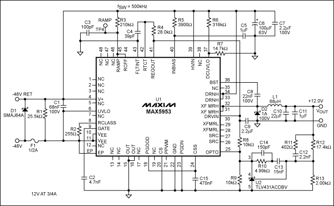
The MAX5953A offers a straightforward, cost-effective, and comprehensive non-isolated power integrated circuit (IC) solution for Powered Devices (PD) in Power-over-Ethernet (PoE) systems. The MAX5953A is designed to facilitate the implementation of Power-over-Ethernet applications by providing an efficient means of...
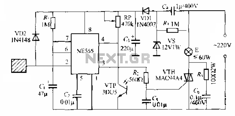
The circuit utilizes a NE553 automatic light sensor composed of 55 groups, allowing lights to turn on when individuals are present and turn off when they leave. The power supply includes VD1, vS, and C, with a 12V DC...

The PIC/Generation 1 electronics lack any form of current limiting. They depend on the resistance of the stepper motors to maintain the current below 2 Amps at 12 Volts. Unfortunately, the more commonly available stepper motors of the size...
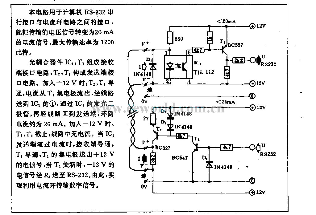
This circuit is utilized in RS-232 serial interface and current loop circuit applications. It converts voltage signals into a 20mA current signal, with a maximum transmission rate of 1200 bits per second. The CCD IC1 and transistor T1 form...
A filter removes the DC component of the rectified AC, which is then scaled to RMS. The output is linear from 40 Hz to 10 kHz or higher. The described circuit primarily consists of a filter designed to eliminate the...
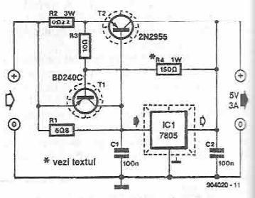
This power supply circuit is designed to provide a high current 5-volt output using a 7805 voltage regulator along with several standard electronic components. The transistor T1 functions as a current limiter. When the voltage across resistors R2 and...