
DC Supply

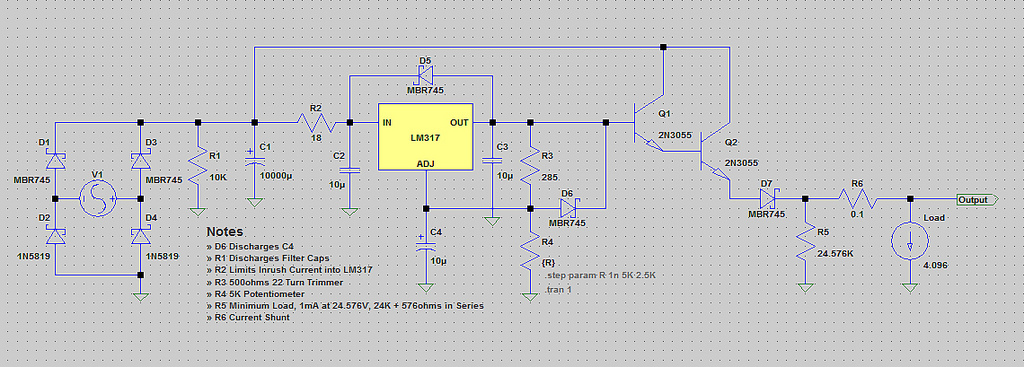
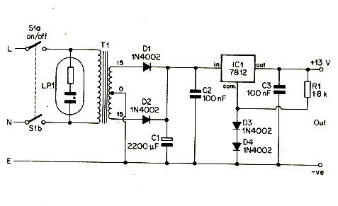
The circuit operates as a linear voltage regulator, designed to provide a stable output voltage while ensuring safety through galvanic isolation. The isolation transformer is a critical component, as it separates the circuit from the main AC line, preventing any direct electrical connection that could pose a shock hazard during experiments with AC voltage.
The linear regulator functions by maintaining a constant output voltage, which is essential for powering sensitive electronic components or devices that require a specific voltage level. The use of an isolation transformer not only enhances safety but also improves the overall reliability of the circuit by filtering out high-frequency noise that may be present on the AC line.
The schematic typically includes input and output terminals clearly labeled for easy connection to the power source and the load, respectively. The input terminal connects to the primary side of the isolation transformer, while the output terminal connects to the load, ensuring that the load receives a stable and isolated voltage supply.
The circuit can be constructed on a universal PCB, allowing for flexibility in component placement and layout. This adaptability is beneficial for prototyping and testing various configurations. The output terminal is designed to handle significant loads, ensuring robust electrical contact and minimizing voltage drop across connections.
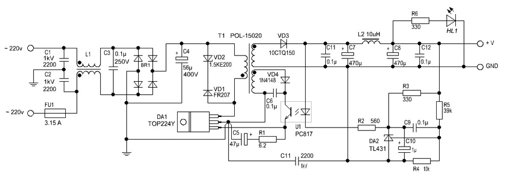
In summary, this linear regulator circuit with galvanic isolation is well-suited for experimental applications involving AC voltage, providing both safety and stability. The careful arrangement of components and the use of an isolation transformer make it an effective solution for powering various electronic projects.The circuit is a linear regulator providing galvanic isolation from main line through the use of isolation transformer. Quite safe for experimenting with AC voltage. Below pictures show the example of input/output terminal connections, labeling and components placement in the box.
The circuit can be built using universal PCB. The output terminal is for big load connection so this makes it quite strong and good electrical contact to the load being used. My workbench has many broken devices and most of them will be used as the part for making the electronic projects. One day I looked at the broken radio, I found there`s an AC line cord with socket and a transformer. Actually I like the way they used 🔗 External reference
Related Circuits
The design is based on the TubeHobby and serves as the power supply used in their NC2. This kit was constructed as an initial project involving nixie tubes, and a review of this excellent kit can be found in...

Universal Power Supply Module 3V-30V power supply. Refer to the specified page for an explanation of the related circuit diagram. This power supply circuit is paired with a high-power audio amplifier rated at 1500 watts. The design of the...
The voltage range will be from 0V to 24V, and the current is not expected to exceed 4A. A microcontroller and an LCD could potentially be added to measure voltage and current. The schematic appears to be generally acceptable....
A 12V portable and mobile power supply circuit design that can be constructed at a low cost and requires minimal circuitry. This circuit provides an output current of 1 amp, which is well stabilized and smoothed. The 12V portable power...
The following circuit illustrates a Power Factor Correction (PFC) Switching Power Supply Circuit Diagram. Features include suitability for 1U (1.75-inch) form factor and minimization of input harmonics. The PFC Switching Power Supply Circuit is designed to enhance the efficiency of...
12 Volt / 2 A Switching Power Supply. Refer to the corresponding page for an explanation regarding the circuit diagram related to the above power supply. The 12 Volt / 2 A Switching Power Supply is designed to convert a...