
12 volt 2 a switching power supply
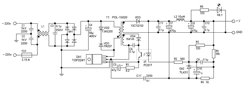
The 12 Volt / 2 A Switching Power Supply is designed to convert a higher input voltage into a stable 12 V output with a maximum current of 2 A. This type of power supply utilizes a switching regulator to achieve high efficiency and compact size. The primary components of the circuit typically include a transformer, rectifier, filter capacitors, and a control circuit.
The operation begins with the input AC voltage being transformed down to a lower AC voltage by the transformer. The output from the transformer is then rectified using a bridge rectifier configuration, which converts the AC voltage to DC. The rectified voltage is smoothed out by filter capacitors to reduce ripple, providing a more stable DC voltage.
The switching regulator, often based on integrated circuits (ICs) such as the LM2596 or similar, is responsible for maintaining the output voltage at 12 V. It does this by rapidly switching the input voltage on and off, controlling the average voltage delivered to the load. Feedback mechanisms are implemented to monitor the output voltage and adjust the duty cycle of the switching to ensure consistent output under varying load conditions.
Protection features may include over-voltage protection, over-current protection, and thermal shutdown to prevent damage to the power supply and connected devices. The design can be further enhanced with additional components such as inductors for filtering and improving transient response.
Overall, the 12 Volt / 2 A Switching Power Supply is a versatile and efficient solution for powering various electronic devices, making it a common choice in consumer electronics, industrial applications, and DIY projects.12 Volt / 2 A Switching Power Supply power supply. Go to that page to read the explanation about above power supply related circuit diagram. 🔗 External reference
Related Circuits
The goals were achieved by utilizing a discrete-component operational amplifier (op-amp) driving a bipolar junction transistor (BJT) complementary common-emitter output stage configured for Class B operation. In this configuration, the output transistors remain off for small output currents, allowing...
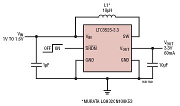
The LTC3525-3/LTC3525-3.3/LTC3525-5 are high-efficiency synchronous step-up DC/DC converters with output disconnect capability that can operate with an input voltage as low as 1V. These converters provide a compact and efficient alternative to charge pumps for single-cell or dual-cell alkaline...
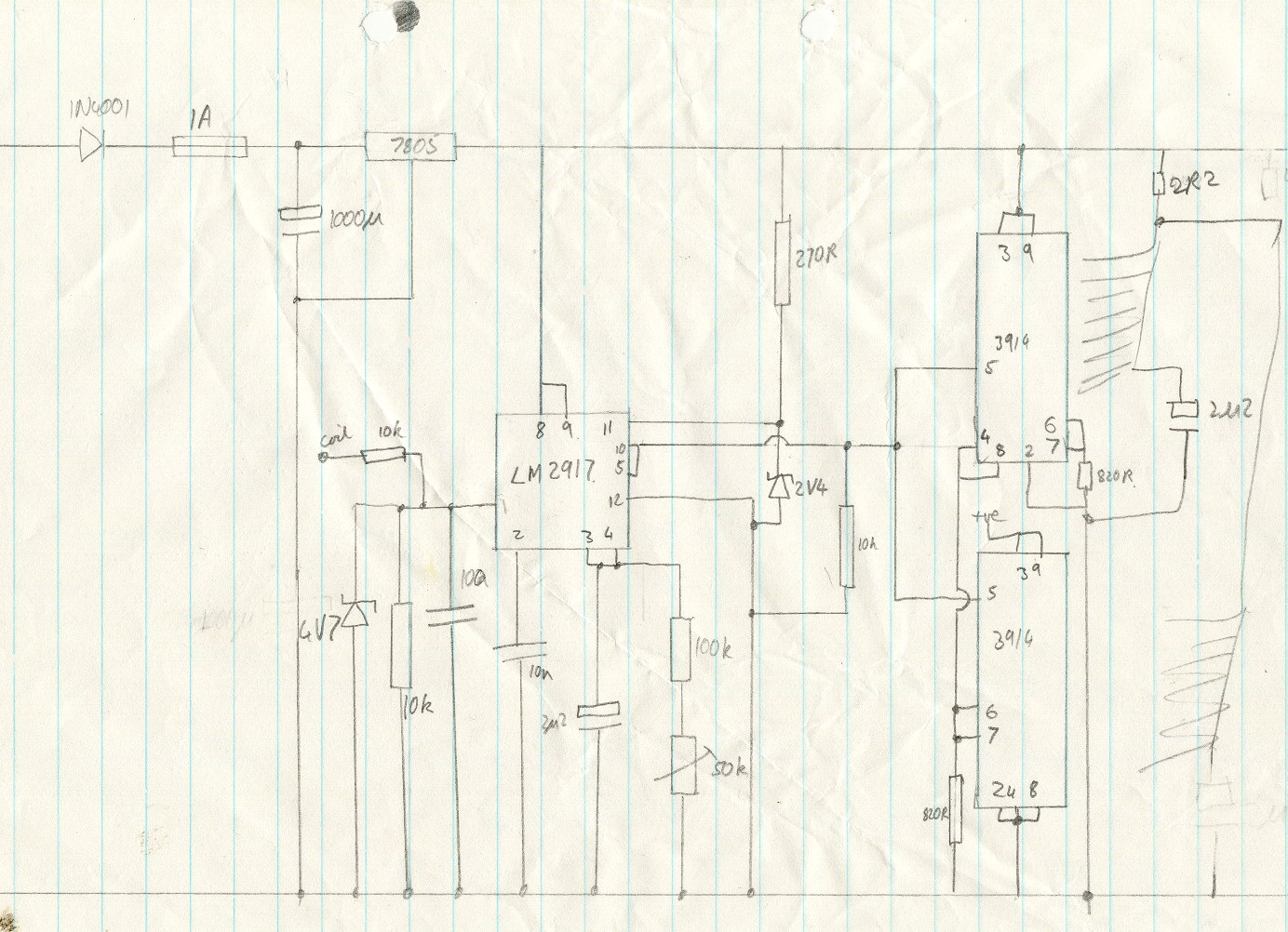
This circuit utilizes an LM2917 frequency-to-voltage converter. The input is connected to the low voltage side of the ignition coil, with various components designed to produce a full-scale output at 6000 RPM, corresponding to 12000 ignition pulses per minute,...
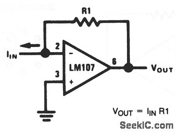
This basic circuit feeds the input current directly into the summing node (pin 2), causing the op-amp output to adjust and extract the same current from the summing node through resistor R1. The scale factor of the circuit is...
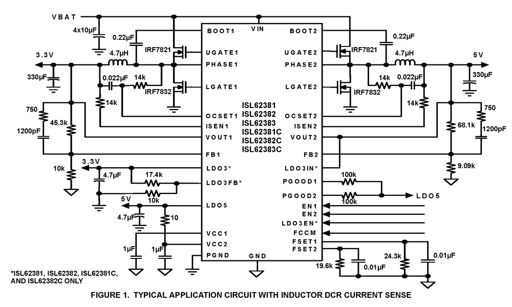
The ISL62381, ISL62382, ISL62383, ISL62381C, ISL62382C, and ISL62383C family of controllers generate supply voltages for battery-powered systems. These controllers include two pulse-width modulation (PWM) controllers, adjustable from 0.6V to 5.5V, and two linear regulators, LDO5 and LDO3, that generate...
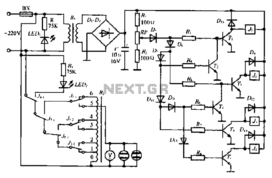
A step-down transformer converts AC 220V to a lower voltage. A diode bridge rectifier and filter capacitor provide a direct current (DC) output, which fluctuates with variations in the grid voltage. A resistive voltage divider is used for sampling....