
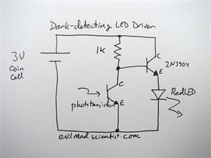
Flasher circuit negative switching

The circuit in question involves resistors that have been verified for accessibility. When measured in isolation—meaning they are not connected to any ground or input sources—the resistors exhibit an open circuit condition. This indicates that there is no continuity through the resistors, which could suggest either that the resistors are functioning correctly (if they are intended to be open in this state) or that there is an issue that requires further investigation.
In a typical electronic schematic, resistors are represented by zigzag lines and are often labeled with their resistance values. The configuration of these resistors within a circuit can significantly affect the overall functionality, such as voltage division, current limiting, and signal attenuation.
To ensure accurate measurements, it is crucial to use a multimeter set to the appropriate resistance measurement mode. The probes should be connected to the resistor terminals without any other circuit components influencing the readings. If the resistors are part of a larger network, it may be necessary to isolate them from the circuit to obtain accurate measurements.
In practical applications, understanding the behavior of resistors in an open circuit condition is essential for troubleshooting and circuit analysis. If a resistor is expected to conduct but measures as open, it may indicate failure or disconnection, necessitating further inspection of the circuit layout and connections.Actually did (do) have access to the resistors but yes measured open (disconnected from any ground source or input source).. 🔗 External reference
Related Circuits
Christmas is approaching, and it is the time of year when electronics students and hobbyists consider creating a Christmas circuit for their homes, particularly one that features flashing lights. Numerous circuits and kits are available that can flash various...
All car batteries require a 12V battery charger, which also applies to marine, RV, and power sports batteries. The high-efficiency lead-acid batteries available today necessitate more effective charging techniques. The battery charger is a crucial tool for prolonging battery...
The circuit is a battery charging system powered by Q2, Q6, R8, and D10, which provides constant current to charge the battery. When an external power supply is present, the charging current flows through R8 and D10 to charge...

The circuit consists of an oscillator with variable frequency, a frequency divider, and a measurement stage. The oscillator is based on an inverter from a 74HC14 and generates a frequency that is inversely proportional to the capacitance of the...
It is entirely logical that low-cost miniature microcontrollers have fewer pins than their larger counterparts, sometimes too few. Consideration has been given to how to economize on pins by making them perform the work of several. It was noted...
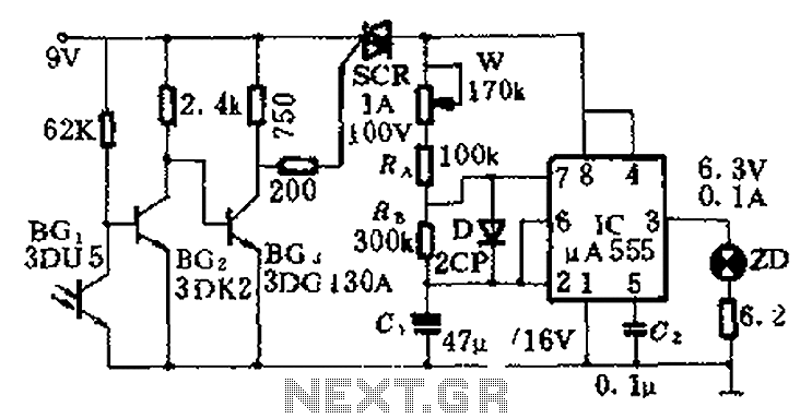
This circuit is designed for nighttime illumination and corridor lighting. During daylight, sufficient light causes BG3 to conduct, preventing the SCR from oscillating. As a result, the circuit remains inactive, and the light does not turn on. At night,...