
Power-inverter
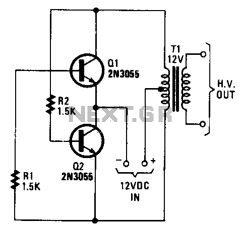
In this circuit design, a transformer is utilized to step down or step up the voltage as required, with options for either 6.3 V or 12.6 V types. When implementing the circuit, a 12 V DC input should be connected such that the positive terminal is linked to the center tap of the transformer. This configuration allows for balanced voltage distribution across the secondary winding, which is essential for proper operation of the subsequent components.
The negative terminal of the power supply is connected to the emitters of two transistors, which can be configured in a push-pull arrangement for efficient amplification or switching applications. This setup enables the transistors to operate effectively, driven by the transformer’s output.
For the output stage, a bridge-type rectifier is recommended. This configuration consists of four diodes arranged to convert the alternating current (AC) signal from the transformer into a direct current (DC) signal. The bridge rectifier ensures that both halves of the AC waveform are utilized, resulting in a smoother and more efficient conversion process.
Following the rectifier, a filtering stage is essential to smooth out the pulsating DC output. Various filter designs can be employed, such as capacitive filters, which use capacitors to reduce voltage ripple, or LC filters, which incorporate inductors for further smoothing. The choice of filtering components will depend on the specific application requirements, including the desired output voltage stability and load characteristics.
This circuit configuration is suitable for various applications requiring a reliable DC power source derived from an AC supply, ensuring efficient operation and minimal voltage fluctuations.The transformer can be any 6.3 or 12.6 V type. Apply the 12-Vde input so the positive goes to the transformer"s center tap and the negative goes to the two transistor emitters. Any bridgetype rectifier and filter can be used at the output, if you need de. 🔗 External reference
Related Circuits
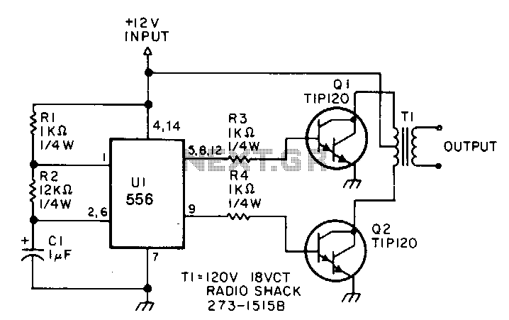
This low-power inverter utilizes only nine components to convert 10 to 16 VDC into a 60 Hz, 115 V square-wave output suitable for operating AC equipment with a maximum power of 25 W. The initial section of the 556...
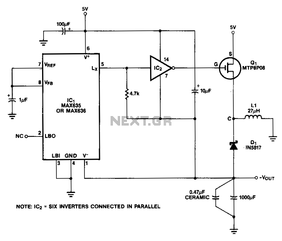
In this circuit, a CMOS inverter, such as the CD4069, is utilized to convert the open-drain Lx output into a signal that is appropriate for driving the gate of an external P-channel MOSFET. The MTP8P03 has a gate threshold...
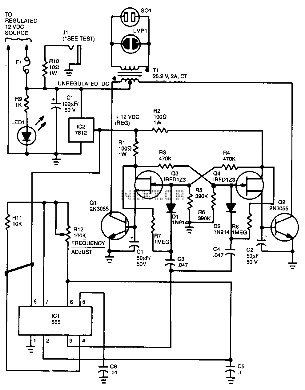
Capacitor C5 and potentiometer R12 determine the frequency of the output signal at pin 3 of IC1, the 555 oscillator. The output signal is differentiated by C3 and C4 before it is input to the base of power transistors...